|
|
||||||||||||||||||||||||||||||||
|
|
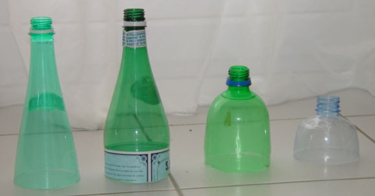
Convergent nozzles with different coefficients of contraction. Best to worst going from left to right. To understand the efficiency of fluid flow. The nozzle coefficient for each duct profile needs to be identified Cf. The design point of the nozzle where the optimum flow is obtained needs to be identified.
|
|||||||||||||||||||||||||||||||
|
|
||||||||||||||||||||||||||||||||
|
|
||||||||||||||||||||||||||||||||
|
Components of the water jet stream |
||||||||||||||||||||||||||||||||

Case1 |

Case2 |
|||||||||||||||||||||||||||||||
|
Case 1:
A steady stream of water pouring from a tap. The diameter of the water cord reduces as the distance below the source increases. Just until a steady state fluid flow system is established. Observation: Note: Look at the form of the water stream. Study the detail of the slow progressive profile/curve as the water stream changes from the larger to the smaller diameter.
The predominant acceleration that influences this process is the acceleration due to gravity or g = 9.81 m/s2. of the mass of water leaving the tap . So the water flow is being accelerated downwards. Towards the center of the Earth. The mass of all objects is affected by gravity.
The further we move this mass away from the center of the Earth the value of g to which it is exposed decreases.
A good example of this is when we see astronauts floating around inside their space modules in orbit around the Earth. They still have the same mass but we now say they are in a very low gravity environment or become relatively 'weightless'.
On the surface of the moon astronauts are able to leap and jump without much effort because the value of gravity on the surface of the moon is much lower than on Earth. gmoon = 1.6 m/s2 or gearth / 6.
On Earth the acceleration due to gravity is g but on another planet this value will be different. Due to its different size, speed of rotation and proximity relative to other planets.
Example: So on the surface of Earth a mass of M = 1Kg will be accelerated towards the center of the Earth by gravity g ( 9.81 m/s2 ). Applying a force of F.
Where F = M * g
Substituting for our example the values of M=1 and g = 9.81 m/s2.
F = 1 * 9.81 F = 9.81 N
So a mass of 1kg creates a force of 9.81N.
Understanding gravitational attraction between two masses. http://www.fourmilab.ch/gravitation/
|
||||||||||||||||||||||||||||||||
|
Case 2:
Now imagine that the predominant acceleration of a rocket mass M1 is that created during the water spike or jet phase. By the rate of change of mass dM of M1 as the water leaves the rocket with a velocity V1.
M1 Is the initial mass. M2 Is the final mass and dM the elemental change in mass after time dt.
Here we need to imagine the progressive change from M1 to M2 being made up of hundreds of small elements or steps each of dt seconds and each with a unique value of dMn. dMn being the change in mass of the rocket for the nth element of duration dt secs. The magnitude of dMn will reflect the efficiency of fluid flow and the design efficiency of the nozzle or duct at that point in time.
As the fluid jet stream leaves the rocket it generates a jet thrust force. Fjet
|
||||||||||||||||||||||||||||||||
|
Here there is an equal and opposite action and reaction.
As defined in Isaac Newton's 3rd Law of Motion published in 'Principia' 1686. 'Action and reaction are always equal and opposite'
Sir Isaak Newton ( 1642-1727 )
In honour of his contribution to science. Today the SI unit of force is called the Newton (N). A force of 1 Newton will give a mass of 1 Kg an acceleration of 1 m/s2.
|
|||||||||||||||||||||||||||||||

|
Next we use the relationship:
F = M * a (1)
Force = Mass * Acceleration.
|
|||||||||||||||||||||||||||||||
|
Force = Rate of change of momentum.
|
||||||||||||||||||||||||||||||||
|
|
Propulsion Force derivation of Tsiolkovsli's formula level2
So the water jet stream mass accelerating downward has a reaction of accelerating the rocket mass Mr upwards. Similarly the downward jet thrust force has an equal and opposite reaction driving the rocket upwards.
Jet Thrust Force Fjet = q* V1
Where q is the mass flow-rate of fluid leaving the nozzle. Kgs/s and V1 is the velocity of the flow m/s
For a full appraisal of the forces involved refer to the 'Force Balance diagram'
There are several components that contribute to accelerate the water jet stream:
1. The compressed air trying to expand down to atmospheric pressure forcing the water out of the bottle. 2. The pull of gravity on the falling water jet cord. 3.And the relative acceleration of the jet stream source. (or Rocket)
The larger the rate of change of mass or the higher the fluid mass flow rate the greater the acceleration of the final rocket mass M2.
Note: Refer to the section on Tsiolkovski Mass Factor for a more detailed explanation as to why mass flow is so important for rocket propulsion. Tsiolkovski Theory 1883 Published 1898
Tsiolkovski Formula V2 = Vin * Ln(M1/M2) m/s
Where Vin Is the initial velocity. V2 Is the final velocity of the rocket. Ln(M1/M2) Is the Natural Logarithm of the mass ratio.
Finally when the mass flow rate falls below that required to produce an equivalent acceleration due to gravity. The projectile M2 begins to decelerate. So after the initial jet acceleration phase the rocket comes under the affect of gravity trying to pull it back to Earth. This deceleration determines the height or apogee to which the rocket will climb after launch.
If we could maintain this high mass flow-rate for long enough we would be able to escape the attraction of the Earth and go for orbit. Like real rockets.
Here is a comparison:
Of our water rocket 'Papillon 2' Tjet.= 0.04>0.056secs hjet = 1.64m mf = 12.25 Kg/sec V = Min 66 m/s M1= 0.750Kgs. Now this is the interesting thing initial acceleration a1 >1000 m/s2 101g but for only 0.04s Measurements of a1 = 2700 m/s2 have been recorded. 275g at 7bar
Because of the very short event times involved we can only approximate the velocities currently based on video recorded launches. But we can see the initial velocity is in excess of 100m/s. Our flight data recordings have a control system delay response that means we cannot record initial accelerations or velocities reliably. Until the rocket is 0.5secs into its flight. We would like some help with the loan of a high speed camera to continue our research. If your interested please contact us. The Leeds University project has recorded peak accelerations of over 4000m/s2or 408g using a launch pressures of 8bar. Note: That this is for a bottle without a nose cone. This type of blunt aerodynamic form is refered to as a 'bluff body'.
Now if we make a comparison with esa 'Ariane 4' Tjet = 342 secs hjet = 167Kms mf = 2000 Kg/sec V = 5400 m/s M1 = 486000Kgs. Flight accelerations taken at the end of each launch phase First stage a1 = 14.23 m/s2 Second stage a2 = 18.56 m/s2
|
|||||||||||||||||||||||||||||||
|
|
||||||||||||||||||||||||||||||||
|
|
||||||||||||||||||||||||||||||||
|
The principle objective is the creation of a stable water spike system. Using the optimum mass flow rate. That will accelerate the final mass of the rocket M2 for the longest duration. Transforming the maximum energy input to the system into stable rocket flight.
Input Energy > Output rocket momentum M2*V2
Energy input to the system: In our case this is the gas spring energy provided by the compressed air.
System or cycle efficiency: The efficiency of the fluid flow system leaving the rocket. The interaction between the external and internal fluid flow systems. Aerodynamic efficiency and dynamic flight stability of the rocket. Note: This later affects the relative accelerations of the jet stream and the rocket.
System output: The acceleration of the rocket mass M2 against the opposing acceleration due to gravity.
Gravity g on Earth tries to pull or attract all objects towards its center. So initially for any object including our rocket to take off. We need to be able to accelerate its mass M2. To overcome this attraction. If not it will rest on the ground. So we can say substituting into formula (1)
Jet Thrust Force Fjet = (M2 * a2) - (M2 * g) - Air Friction Drag (2)
Note: To simplify the equation we will assume that the friction term is negligible. Refer to the force balance diagram for a true force balance. Performance Parameters Table.
Researching the relationship between launch efficiency with the form of water jet spike produced. The form and shape of the water spike is determined by several parameters.
These will all vary with incremental time.
Comparison : |
||||||||||||||||||||||||||||||||
|
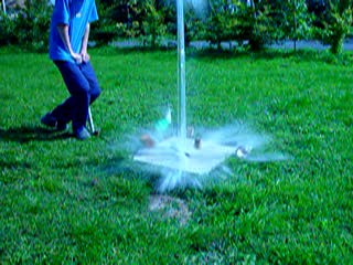
Now imagine that just for a fraction of a second t =< 0.04secs Our water spike experiences an upwards acceleration significantly greater than g gravity. Then the jet spike would look like this....
|
||||||||||||||||||||||||||||||||

©John Gwynn and sons Mercredi 18 septembre 2002 15:27:36
|
.........or this |
|||||||||||||||||||||||||||||||
|
|
||||||||||||||||||||||||||||||||
|
Different types of jet stream signature |
||||||||||||||||||||||||||||||||

Helix or twister jet spike.
|

Curved jet stream.
|
|||||||||||||||||||||||||||||||
|
Helix or twister jet spike: This type of jet stream indicates that the fluid flow has been spun tangentially around the axis of the rocket. This could be due to either the rocket spinning or to a fluid flow system generated by the bottle/ nozzle design. Some of the fluid swirl could be due to the inclination of the rocket at launch creating an elliptical liquid air interface. Encouraging unstable fluid flow as air and water swirl and combine in a vortex like water leaving a bath. Curved jet stream. This curved and intermittent jet stream is the result of unstable rocket aerodynamics generating centrifugal forces that result in a 'swirl and slosh' instability within the working fluid at the nozzle inlet. This is made worse by the inclination of the launch angle. Encouraging unstable fluid flow at the nozzle early in the jet propagation phase.
|
||||||||||||||||||||||||||||||||
|
Discussion: Possibly the water spike shape and generated volume created during launch is defined by the parameters listed above. So subsequently this launch signature could be used as a record of what has actually happened during this very short time interval. During the creation of the ' launch spike' With flight data logging. The flight dynamic performance of the rocket can be defined for a certain type of jet stream behaviour or signature.
The shape and form of the water spike will also reflect the rate of change in mass flow leaving the nozzle.
|
||||||||||||||||||||||||||||||||
|
|
||||||||||||||||||||||||||||||||
Simple experiment to define the different phases of expansion.We advise you use Virtualdub to watch the film images in slow motion
|
||||||||||||||||||||||||||||||||
|
|
||||||||||||||||||||||||||||||||
|
|
||||||||||||||||||||||||||||||||
|
|
|
|||||||||||||||||||||||||||||||
|
|
||||||||||||||||||||||||||||||||
|
Experiments and Research
|
||||||||||||||||||||||||||||||||
|
In search of the parameters that influence acceleration Water rocket explorer |
||||||||||||||||||||||||||||||||
|
Leeds University Water Rocket project 2003. Dr Johannes Knapp
Department of Physics and Astronomy, University of Leeds, Leeds LS2 9JT, UK Students Martin Mansfield A.Parkinson Stuart Weston University Technician. The effect of bottle design on water rocket performance
|
||||||||||||||||||||||||||||||||
|
Coke 2143ml
Bottle 'A' is a standard 2145ml Coke bottle. 8bar Launch images recorded to a height of 2.4m |
Comparisons of the two different bottle types identified differences between the mathematical model predictions and the actual rocket performance. Simple thrust force T = 2PAn and thermodynamic expansion expressions assuming adiabatic expansion for an ideal gas are used for the model of the cycle. P0.V0g = P.Vg..
Conventional height and velocity against time curves generated from the high speed film images produced some unexpected acceleration curves. A clearly none linear acceleration characteristic was identified during the jet pulse event. These experiments where repeated for a range of launch pressures ranging from 5 to 8 bar The importance of efficient energy conversion during the first 0.1secs after launch is identified
Notes by John Gwynn: Recognising the limited resource available on such a project means that some of the questions that are raised during the first phase of the project cannot be answered within the time available. Below I have tried to identify some of my thoughts:
A full interface model of the projectile with its environment , the feedback forces involved and how they effect the overall projectile system efficiency .has not been achieved. How these variable parameters affect both the external and internal fluid flow systems. How the acceleration loads created during the initial jet phase effect, the nozzle efficiency, flight stability dynamics and changes in aerodynamic drag force. Could well contribute to the nonlinear character of the acceleration values recorded during each jet phase. Whilst the existing mathematical model predicted the performance of bottle 'A' fairly accurately at lower pressures. It fails to predict the none linear acceleration change in performance at higher launch pressures. Or identify the differences in initial jet impulse conversion efficiency seen with the two different bottle types. The corresponding full flight data for the rocket after the initial launch phase could be used to quantify the overall flight performance, correlated to a specific high speed launch film. The effect of different aerodynamic drag coefficients are recognised but not quantified. Due to the lack of time and resources available. A good effort and a good base for the next research team.. . A suivre ...... Compares the initial launch phase of two different types of bottle filmed at 500 images per second to a height of 2.4m. Here the image sequence is run for bottle A and is made up by stringing together some of the images. The background scale graduations are at100mm intervals. |
|||||||||||||||||||||||||||||||
|
Click on image to load film 4.7Mb |
||||||||||||||||||||||||||||||||
|
Rocket launch of bottle 'A' 2145ml |
||||||||||||||||||||||||||||||||

|
||||||||||||||||||||||||||||||||

|
||||||||||||||||||||||||||||||||
|
Badoit 1000ml
Bottle 'B' is a standard 1000ml Badoit bottle. 8bar Launch images recorded to a height of 2.4m. |
||||||||||||||||||||||||||||||||
|
Click on image to load film 4.7Mb |
||||||||||||||||||||||||||||||||
|
Rocket launch of bottle 'B' 1000ml |
||||||||||||||||||||||||||||||||

|
||||||||||||||||||||||||||||||||

|
||||||||||||||||||||||||||||||||
|
||||||||||||||||||||||||||||||||
|
|
||||||||||||||||||||||||||||||||
Expansion nozzles |
||||||||||||||||||||||||||||||||
17.09.2002 |
||||||||||||||||||||||||||||||||
|
|
Research: This image extracted from an early video. Captures what we think is the very start of the final mixed fluid spray burst. At T 0.04s Note that the formation is in an upward 'V' shape. Seen at the top of the water spike. Possibly indicating that the expansion spray cloud is being pulled by a low pressure area created by the aerodynamics of the rocket .Due to there being no divergent expansion nozzle. or the mixed fluid plume having a upward vertical velocity/ acceleration component..
So on leaving the nozzle it might not be fully contributing to the downward jet thrust. Or it is the arms of the spray burst being pulled upwards due to the relative acceleration of the discharged mass of the jet plume.. Indicating the start of the development of the future stretched elliptical spray cloud. See launches section |
|||||||||||||||||||||||||||||||
|
|
|

|
||||||||||||||||||||||||||||||
| Image 270 | Image271 |
Image 273 |
||||||||||||||||||||||||||||||
|
1. The first image shows a clean water jet spike shape just after the rocket has left the top of the image. |
||||||||||||||||||||||||||||||||
|
2. The second shows the water jet spike still stretching upwards and reducing in diameter due to the water jet mass still having an upwards velocity. With signs that the regular form shape of the jet column is beginning to break up. The mixed fluid air burst has created a stretched elliptical spray cloud. With the major axis aligned with that of the axis of the rocket nozzle as it displaced vertically. There is a higher density of water droplets along the vertical axis and towards the top.
|
||||||||||||||||||||||||||||||||
|
3. Whilst the third shows the mass of the water making up the jet stream breaking up and fall back irregularly towards the earth. Water droplet density is more uniform with a grouping towards the bottom as the droplets begin to fall under the now predominant influence of Earth's gravity.
|
||||||||||||||||||||||||||||||||
|
|
||||||||||||||||||||||||||||||||
|
High energy Water jet behaviour on impact |
||||||||||||||||||||||||||||||||

|
||||||||||||||||||||||||||||||||
|
Materials and fluids behave differently when exposed to high energy impacts. Here on the left the high energy water jet impacts the surface pulling with in a very thin layer of air. Forming a sought of trumpet shape at the bottom of which the liquid air form becomes unstable and breaks up or fractures. So now you know a high energy water jet can fracture like glass!
|
||||||||||||||||||||||||||||||||
|
|
||||||||||||||||||||||||||||||||
|
Fixed expansion nozzle with a variable angle nozzle on the right that can be rotated If you need to compare the current level of our understanding of water jet propulsion then 'Nature' provides some wonderful examples. The squid provides a very interesting example of variable angle water jet propulsion.
Tip. Look at your http address bar and change the title to sea.
http://seawifs.gsfc.nasa.gov/OCEAN_PLANET/HTML/squid_move.html Tip. Insert nasa into http address.
|
||||||||||||||||||||||||||||||||
|
History of rocket nozzle design Courtesy Boeing Aerospike rocket jet engine 1992. Now imagine that the air flowing around the exterior of the water rocket could affect/control the divergent nozzle cone !
Providing there was no separation of the boundary layer
|
||||||||||||||||||||||||||||||||
|
http://www.boeing.com/defense-space/space/propul/XRS2200.html http://www.aerospaceweb.org/design/aerospike/
|
||||||||||||||||||||||||||||||||
29/09/06
©John Gwynn and sons2003
You're welcome to reproduce any material on this site for educational or other non commercial purposes
as long as you give us proper credit (by referring to "The Water-Rocket Explorer" http://waterocket.explorer.free.fr).