Engineering
at Boeing
Fluids boeing
 
Boeing Engineering Papers
Rocketdyne's engineering journal of power technology

Nozzle Design


by R.A. O'Leary and J. E. Beck, Spring 1992

Superior nozzle design is the culmination of carefully determined mission needs, established physics parameters and hard-earned experience. Rocketdyne's (now Rocketdyne Propulsion and Power, a part of The Boeing Company) contributions to the art began with pioneering rocket propulsion and are now being applied to the state of the art in hypersonic flight.


An aerospace vehicle, whether an aerospace plane, orbital launch vehicle or interplanetary spacecraft, is accelerated by a propulsion system to a velocity dictated by requirements specific to the vehicle's mission. In all cases, a nozzle is used to extract the maximum thrust from high-pressure exhaust gases generated by the propulsion system. The nozzle provides the thrust necessary to successfully accomplish these missions, with high nozzle efficiency translating to greater payload or other mission-related capabilities.

Specifically, the nozzle is that portion of the engine extending beyond the combustion chamber. Typically, the combustion chamber is a constant diameter duct into which propellants are injected, mixed and burned. Its length is sufficient to allow complete combustion of the propellants before the nozzle accelerates the gas products. The nozzle is said to begin at the point where the chamber diameter begins to decrease.


Above, the static pressure at the exit of the Space Shuttle Main Engine nozzle is considerably less than ambient pressure at sea level, a mismatch in pressure that gives rise to the striking Mach disc in the nozzle exhaust. The "disc" is an extremely strong shock wave that creates a region of subsonic flow and produces a characteristic white luminescent glow.

Decreasing flow area results in subsonic (Mach number < 1) acceleration of the gas. The area decreases until the minimum or "throat" area is reached. Here the gas velocity corresponds to a Mach number of one, denoting that the flow velocity is equal to the local speed of sound of the particular gas. Then the nozzle accelerates the flow supersonically (Mach number > 1) by providing a path of increasing flow area.

Simply stated, the nozzle uses the pressure generated in the combustion chamber to increase thrust by accelerating the combustion gas to a high supersonic velocity. The velocity that can be achieved is governed by the nozzle area ratio (i.e., the nozzle exit area, divided by the throat area) which in turn is determined by the design ambient pressure-the atmosphere into which the nozzle discharges. Low ambient pressure (encountered at high altitudes) leads to a high nozzle exit area, higher gas exit velocity, and hence, more thrust. High thrust efficiency is achieved as a result of careful design of the nozzle shape or contour.

For an ideal one-dimensional (1-D) flow where the gas properties (e.g. pressure, velocity, etc.) are uniform at any point in the flow direction, thrust is simply the gas momentum at the nozzle exit, minus the influence of pressure.

In a vacuum or space application, the maximum theoretical performance would be realized by an ideal nozzle with infinite exit area that would expand the combustion gases to zero pressure thereby attaining the maximum gas velocity which can be expressed as vMAX.

Since the engine flow rate is fixed by chamber pressure, propellant mixture ratio and the nozzle throat area, the nozzle increases thrust by achieving as much of vMAX as possible, given practical limitations of size, weight and operational altitude. Low altitude operation, of course limits the amount of nozzle expansion available because of higher ambient pressure. If ambient pressure is excessive, the engine exhaust flow will be separated from the nozzle wall and large nozzle side loads may develop due to the random uneven separation of the exhaust jet. These loads must be included in the nozzle structural design process.


A nozzle generates thrust by converting the thermal energy of hot combustion gases (temperature) to kinetic energy (velocity). Maximum theoretical thrust is achieved in vacuum conditions when the nozzle area ratio is infinite.
(Click image for larger version.)


Again, assuming a 1-D flow of a perfect gas, the, gas properties at any nozzle area ratio can be obtained by knowing a property of the gas called the ratio of specific heat capacities, or gamma (g). Using well-known compressible flow equations for a perfect gas, tables of flow properties have been generated for different values of g. Fromthese tables, gas velocity, Mach number and the nozzle thrust coefficient (Cf - defined as the thrust divided by the product of chamber pressure and the throat area) are obtained as a function of nozzle area ratio and g.

With a perfect gas, g remains constant throughout the expansion process. However, when the engine flow is composed of hot combustion products, real gas effects dominate. So as the gas expands, g shifts as a result of changes in temperature and the chemical composition.

Maximum thrust is obtained if the gas composition is in chemical equilibrium throughout the entire nozzle expansion process. For this to occur, the chemical reactions must be infinitely fast to allow the gas composition to adjust to rapidly changing pressure and temperature conditions in the nozzle flow field. One-dimensional equilibrium (ODE) thermochemistry codes are currently used to accurately account for shifting g effects on 1-D nozzle performance.

In reality, however, nozzle flow fields are at least two-dimensional (2-D) in nature; that is, flow properties vary in both the axial and radial directions. In a conventional bell nozzle, the gas flowing from the combustion chamber and through the nozzle throat must be turned away from the nozzle axis in order to accelerate or expand the flow. Subsequently, the flow must be turned back parallel to the nozzle axis to maximize nozzle efficiency. Throughout the 1960s, Rocket-dyne developed an extensive library of computer programs that address the 2-D nature of supersonic flow fields using a computational procedure called the method-of-characteristics, or MOC. These computer programs, some still unique in the propulsion industry, are in current use for designing and analyzing both conventional bell nozzles and unconventional types such as aerospike and expansion-deflection (E-D) nozzles.

The MOC technique begins with a series of points describing the flow field (i.e., Mach number and flow direction) along a "start line." The start line is generated by a transonic (0.8 < Mach number < 1.5) flow field analysis of the throat region. Using these points and the geometry of the nozzle contour, the solution proceeds downstream point-by-point, thereby creating a network of points and lines referred to as a characteristic "net."

For conventional bell nozzles, loss mechanisms fall into three categories: (1) geometric or divergence loss, (2) viscous drag loss, and (3) chemical kinetics loss. Geometric loss results when a portion of the nozzle exit flow is directed away from the nozzle axis, resulting in a radial component of momentum. In an ideal nozzle, the exit flow is completely parallel to the nozzle axis and possesses uniform pressure and Mach number. By calculating the momentum of the actual nozzle exit flow and comparing it to the parallel, uniform flow condition, the geometric efficiency (hgeo) is determined. By careful shaping of the nozzle wall, relatively high geometric efficiency can be realized; for example, hgeo for the Space Shuttle Main Engine (SSME) nozzle is 0.992 (0.8 percent thrust loss compared to ideal).

A drag force, produced at the nozzle wall by the effects of a viscous high-speed flow, acts opposite to the direction of thrust, and therefore results in a decrease in nozzle efficiency. This viscous drag efficiency is defined as:


The drag force is obtained by calculation of the momentum deficit in the wall boundary layer. The predicted value for the SSME is 0.986 (1.4 percent loss due to viscous drag).

The third nozzle loss mechanism is due to finite-rate chemical kinetics. Ideally, the engine exhaust gas reaches chemical equilibrium at any point in the nozzle flow field, instantaneously adjusting to each new temperature and pressure condition. In real terms, however, the rapidly accelerating nozzle flow does not permit time for the gas to reach full chemical equilibrium. The chemical kinetics efficiency is calculated by comparing the one-dimensional kinetics (ODK) solution to the ODE solution, or:


Because the SSME is designed to operate at high chamber pressure (roughly 3,000 psia) and the chemical reactions involving hydrogen and oxygen are not complex, the chemical reaction rates in the SSME are extremely fast; conse- quently, the SSME kinetic efficiency is high:


The overall nozzle efficiency is then given by the combined effects of geometric loss, viscous drag and chemical kinetics:


The two-dimensional kinetics (TDK) computer program, which has been combined with a boundary layer module (BLM), is the industry standard JANNAF (Joint Army-Navy-NASA-Air Force) program which accounts for all three nozzle losses and is used to predict hnoz for conventional bell nozzles.

Experience tells the nozzle designer that a long nozzle is needed to maximize the geometric efficiency; but at the same time, nozzle drag is reduced if the nozzle is shortened. If chemical kinetics are an issue, then the acceleration of exhaust gases at the nozzle throat should be slowed by increasing the radius of curvature applied to the design of the throat region. The optimum nozzle contour is a design compromise that results in a maximum overall nozzle efficiency.

There are several classes of bell-type nozzles from which to choose. A nozzle contour designed to produce parallel, uniform exit flow, thereby


Optimum nozzle configuration for a particular mission depends upon system trades involving performance, thermal issues, weight, fabrication, vehicle integration and cost.


yielding 100 percent geometric nozzle efficiency, is called an ideal nozzle. But this ideal nozzle is extremely long and the high viscous drag and nozzle weight that result are unacceptable. Some design approaches consider truncating ideal nozzles until the weight considerations, hgeo and hdrag are optimized.

The most basic contour that can be considered for a nozzle is a truncated cone. Conical nozzles yield nearly uniform exit velocity, but the flow angle varies from zero at the axis to the cone half-angle at the wall. Consequently, flow divergence is introduced, which can be expressed as:


where a is the cone half-angle. A 15° half-angle yields a geometric nozzle efficiency equal to 0.983 and is typically two-thirds the length of an ideal nozzle. For low-area-ratio nozzles, where simple fabrication methods are desired, 15° cones have become an accepted standard. The length of any nozzle type is commonly referenced to the length of a 15° cone having the same nozzle area ratio.

It had long been assumed that for a given nozzle area ratio and length, there existed a unique nozzle contour that would yield the maximum geometric nozzle efficiency or maximum thrust. In the late 1950s, Dr. G.V.R. Rao derived a method for analytically defining this unique contour. His method is widely accepted by the propulsion industry, and any nozzle contour designed for maximum thrust for a given nozzle area ratio and length is referred to as a Rao optimum contour. By shaping the nozzle wall according to Rao's method, a shorter nozzle and an improvement of over one percent in nozzle efficiency can be obtained relative to a 15° cone.

Nozzle contours can also be designed for reasons other than for maximum thrust. For example, contours can be tailored to yield certain desired pressures or pressure gradients to minimize flow separation concerns at sea level. Rocketdyne has a parabolic curve-fit program, generally used to approximate Rao optimum contours, which can also be used to generate desired nozzle wall pressures.

Early booster engines typically incorporated conical nozzles to simplify fabrication. Since booster engines perform only at low altitude and are then jettisoned, peak nozzle efficiency has less of an impact on the total mission. The SSME, however, is used from sea level to orbit insertion. Its nominal thrust time is eight minutes for each mission, and efficient use of the propellants is a prime consideration.

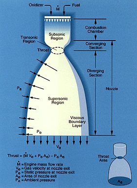
The SSME nozzle is 10.3 inches in diameter at the throat, increasing to 90.7 inches at the nozzle exit over a length of 121 inches. At 100 percent power level, propellants flow through the nozzle at a rate of 1,035 pounds per second. The nozzle accelerates the combustion products to 17,000 feet per second at the nozzle exit, generating 470,000 pounds of thrust at vacuum. Because the last one percent of SSME thrust at a fixed mass flow rate translates to about 5,000 pounds of shuttle payload, high priority was placed on nozzle design and performance.

The SSME nozzle configuration was the result of a number of design iterations. Various system studies and mission optimizations showed that high nozzle area ratio was critical and the nozzle was configured with an area ratio of 77.5:1, and a length equal to 80 percent of a 15° conical nozzle. The task left to the nozzle designers was to specify the shape of the nozzle contour from the throat to the nozzle end point which was dictated by the area ratio and nozzle length.

The first choice for an SSME nozzle contour would obviously be one that maximized nozzle thrust; that is, a Rao optimum contour. However, if a Rao optimum contour was used, the wall pressure at the nozzle exit, (pw(exit)) would be much lower than the ambient pressure at sea level. Even at 100 percent power levels, corresponding to a chamber pressure equal to 3,000 psia, (pw(exit)) would be 4.6 psia or 31 percent of the ambient pressure at sea level. Past experience showed that nozzle flow separation would likely occur if the wall pressure approached this level. Since nozzle flow separation is dependent upon a number of variables (boundary-layer thickness, pressure gradient, Mach number, etc.) and is thus difficult to accurately predict, additional margin in exit pressure was sought. Some margin was also required to permit sea-level testing of engine throttling capability.

A Rao design resulted in a wall angle of 7.5° at the nozzle exit. By reducing this angle, additional flow turning is produced, and then, an increase in nozzle wall pressure is created. A study was performed by Rocketdyne engineers in which a large number of parabolic-shaped contours, with a variety of different initial wall angles (qmax) and exit wall angles (qe), were analyzed. After careful analysis of these contours, it was determined that a parabolic contour with qmax=37° and qe=5.3° would produce the desired wall pressure increase with the least amount of performance loss. The wall exit pressure was raised 24 percent (from 4.6 psia to 5.7 psia) at a cost of only 0.1 percent in nozzle efficiency. Validation of the design approach was provided by subsequent testing of the SSME which demonstrated that the engine can be throttled to below 80 percent power level at sea level without nozzle flow separation.

Since more of the SSME operation is at high rather than low altitude, vacuum performance is the overriding factor relating to mission performance and high nozzle area ratio is therefore desirable. However, nozzle over-expansion at sea level does result in a thrust loss because the wall pressure near the nozzle exit is below ambient pressure. If the nozzle exit area could somehow be reduced for launch and then gradually increased during ascent, overall mission performance would be improved. The ideal rocket engine would make use of a continuously changing "rubber" or variable-geometry nozzle that adjusted contour, area ratio and length to match the varying altitude conditions encountered during ascent. This feature is referred to as altitude compensation.

For single-stage-to-orbit (SSTO) applications, where performance margins are even more stringent than for the SSME, some form of altitude compensation in the nozzle is a must. An SSTO vehicle relies on a single propulsion system that operates from sea level to orbit. The aerospike engine, built and tested by Rocketdyne in the 1960s, is currently being evaluated for potential use with an SSTO vehicle because of its built-in altitude compensation features and the beneficial manner in which it "packages" or integrates with the vehicle.

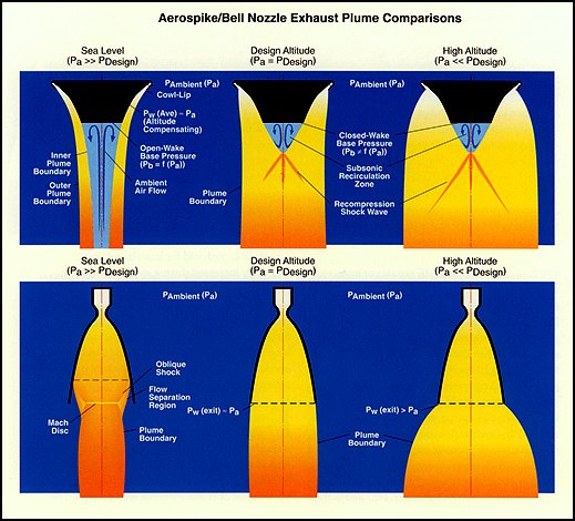
In the annular aerospike nozzle, flow issues from an annulus at a diameter located some radial distance from the nozzle axis. Flow is directed radially inward toward the nozzle axis. This concept is the opposite of a bell nozzle which expands the flow away from the axis along diverging nozzle walls. In an aerospike, the nozzle expansion process originates at a point on the outer edge of the annulus which is referred to as the "cowl-lip." Because this point is also exposed to ambient pressure, the flow turning or


The altitude compensating feature of the aerospike results from exposure of the nozzle expansion process to the effect of ambient pressure. High ambient pressure limits expansion at the cowl-lip and prevents the flow from becoming highly over-expanded at sea level. In a high-area-ratio bell nozzle the flow can over-expand to the point where the flow separates from the nozzle wall, producing undesirable lateral forces. As the ambient pressure decreases with increasing altitude, the nozzle exhausts for both the aerospike and the bell nozzle are capable of greater expansion.
(Click image for larger version)


expansion is limited by the influence of the external environment. In a standard bell nozzle, flow expansion continues regardless of what the ambient pressure is, and the flow can con tinue to over-expand until it separates from the nozzle walls.

With an aerospike nozzle, ambient pressure places a limit on the expansion process and the thrust loss associated with nozzle over-expansion does not materialize. In addition, the benefits of a variable area ratio nozzle are gained without the complexities associated with variable nozzle geometry. Since ambient pressure controls the nozzle expansion, the flow area at the end of the aerospike changes with altitude. A key advantage of an aerospike is that a very high area ratio nozzle, which provides high vacuum performance, can also be efficiently operated at sea level.

Given the nozzle area ratio, which, for an aerospike, is a function of engine chamber pressure, required thrust level and vehicle diameter, an ideal "spike" contour can be designed by starting with the known 1-D exit Mach number - which is a function of area ratio - and performing a "reverse expansion" back to the nozzle throat (Mach number=1). The resulting ideal spike contour yields parallel, uniform exit flow, but is, however, excessively long. Since wall pressures and projected nozzle area are minimal toward the end of the "spike," significant length can be eliminated before the loss in thrust becomes excessive. For example, the length of an ideal spike is about 150 percent of a 15° cone. Weight versus nozzle performance trades typically re- duce the nozzle length to the 20 percent range.

Truncation of the full length "spike" results in the formation of a nozzle base region and a performance loss. However, the thrust pro duced by the discarded portion of the spike is not entirely lost. At high altitude, the nozzle flow at the end of the truncated nozzle turns into the base and surrounds a "bubble" of recirculating subsonic flow. Since the wake is closed, no external or ambient influence can be exerted. The important result is that a pressure exists on the nozzle base that partially offsets the truncation loss. Data generated from a variety of cold-flow aerospike tests revealed that the base thrust is a fixed percentage of the thrust generated by the discarded portion of the spike. Knowing the base area (Ab), an average base pressure (Pb) is thus empirically determined for the closed wake case.

High base pressure is, of course, desirable. One common method used for increasing base pressure is the introduction of a secondary gas into the base region. It was found that by injecting secondary flow equal to about one percent of the primary engine flow, engine performance would be optimized. Use of secondary flow in the base also elongates the separation bubble, thereby forming an "aero-dynamic" contour that resembles the truncated portion of the spike. This aerodynamic spike, formed by use of secondary base flow, is the basis for the term "aerospike."

At the nozzle pressure ratio (NPR - chamber pressure divided by ambient pressure) where the exit flow of an ideal aerospike is at a uniform velocity and at a constant plume diameter (equal to the engine "cowl-lip" diameter), the engine is said to be operating at the "design" condition. At low NPR or low altitude operation, the high ambient pressure "squeezes" the exhaust plume inward toward the nozzle wall. As a result, low altitude operation is characterized by the appearance of a series of alternating pressure peaks and valleys along the nozzle surface.

The reason for these wall pressure oscillations is found by inspection of a MOC flow field analysis. The expansion at the cowl-lip proceeds until the flow reaches ambient pressure, creating a series of expansion waves that propagate downstream toward the nozzle wall. At the point where the last expansion wave in the series intersects the wall, the wall pressure is near the ambient value. Further expansion is not possible, but the supersonic exhaust gas continues to be gradually turned parallel to the nozzle axis by the contour. This results in a compressive turning region on the nozzle where the wall pressure rises and eventually exceeds the ambient pressure, in some cases by a considerable amount. The resulting compression waves propagate outward toward the constant pressure plume boundary that is established between the engine exhaust gas and the vehicle slipstream.

These compression waves reflect from the plume boundary in the form of a series of expansion waves that eventually intersect the nozzle wall downstream of the compression zone. The expansion waves then begin to relieve the high pressure on the wall and a zone of low pressure is thus created downstream of the compression zone. The minimum pressure experienced in this low- pressure zone is typically less than the ambient pressure. When the last expansion wave in the series intersects the nozzle wall, the wall pressure begins to rise again due to the gradual turning caused by the nozzle contour. The process then repeats itself, setting up an alternating series of high- and low-pressure zones on the nozzle wall. Since the average wall pressure is typically greater than the ambient pressure, the flow is not over-expanded.

By allowing the influence of ambient pressure to be transmitted to the nozzle wall, the aerospike yields a net thrust advantage over conventional bell-type nozzles.

Another important aspect of the low altitude performance of aerospike nozzles relates to the


Above, two techniques for analyzing the two- dimensional supersonic flow field of a nozzle are method-of- characteristics (MOC) and computation fluid dynamics (CFD). Both techniques predict the wall pressure oscillations that are characteristic of an aerospike nozzle when operated at sea-level conditions.

pressure acting on the nozzle base. When the nozzle pressure ratio is less than roughly one- third of the design pressure ratio, the wake that is present in the base of the plug is said to be "open," meaning that the base is open to the influence of ambient pressure and the base pressure is a strong function of the ambient pressure. This condition is distinctly different from the condition that occurs on the base for high-altitude operation where the wake is "closed," and the base pressure is independent of the ambient pressure.

As in the case of a closed wake, an increase in performance can be realized by bleeding secondary flow into the base of the plug. The addition of mass into the base increases the base pressure and the resulting base thrust contribution.

When a vehicle is accelerated through the atmosphere, the air flowing over the vehicle can strongly influence the altitude-compensating characteristics of the aerospike. At flight speeds corresponding to a Mach number just below one, the vehicle slipstream has been shown to improve nozzle performance by a small amount. However, from Mach 1 to about Mach 3, wind tunnel tests indicate a drop in nozzle efficiency due to the slipstream turning into the nozzle region. When this occurs, the local pressure into which the engine exhausts drops below ambient pressure, and the nozzle flow field adjusts to an effectively higher altitude. As a result, the pressure peaks on the nozzle surface are reduced, and overall performance suffers. Nevertheless, the interval of time that is spent in this adverse flight regime is short for typical flight trajectories, and the overall performance of the aerospike nozzle remains well above that of a conventional bell-type nozzle.

With use of computational fluid dynamics (CFD), tremendous opportunities arise to accurately analyze complex nozzle flow fields that in the past could only be resolved by costly experimentation. For example, advanced nozzle concepts, such as the aerospike, introduce flow field complexities that include three-dimensional (3-D) multiple thruster effects, slipstream


During the 1960s, Rocketdyne tested numerous aerospike engines, ranging in size from subscale, cold-flow models to this 250,000- pound-thrust oxygen/ hydrogen engine shown at a test stand in Nevada. The low altitude performance advantage of the aerospike over the conventional bell nozzle is clearly seen.


interactions and separated base flows. Design of a system to control vehicle flight by adjusting the angle and location of the nozzle thrust vector also relies on CFD analysis. Thrust vector control is often achieved by throttling individual thrusters or by injecting gas through the nozzle wall to cause a change in the local pressure distribution. In either case, complex 3-D flow fields are generated which can only be analyzed by use of CFD.

The challenge now facing nozzle design engineers is the future development of CFD as a design tool. In this mode, CFD would arrive at a nozzle contour that would produce a desired result, such as maximum overall nozzle efficiency or a specified nozzle wall pressure distribution. The key to future development lies in the ability to use expert or knowledge-based systems to transform existing CFD computer programs into useful nozzle design tools.

 
Home
Site Map | Contact Us


Copyright © 2002 The Boeing Company. All rights reserved.