Time the flight.
|
Archive 1995 Launch Alex 5 and Gabriel 2.5
|
||
|
|
|||
|
Guillotine or sprung gate, flange lock release. This type of launcher uses a sprung gate that locks above the external bottle neck flange.
Launch Procedure:
Advantages:
Disadvantages: |
|
||
|
|
|||
|
|
||
| High pressure caps.
This is a type of launch tube that allows the compressed air charge to be built up in the tube volume in the base of the launcher to a preset pressure controlled by a special pressure cap. Once reached the compressed air charge is released in a small diameter light weight tube rocket.
|
|
||
|
|
|||
|
|
|
||
|
|
|||
|
Launch site selection and preparation.
|
|
||
|
|
|||
|
Supply services to the launch site:
From late spring through to the first frost we use a garden water supply using Gardena water fittings. During autumn and winter we use warm water to charge both the launcher and the rocket in addition to using another bottle of hot water used like a hot water bottle to keep the pump and valves from freezing up when the temperature are below zero. We also put the pump on the radiator to warm in through before taking it outside.
|
|||
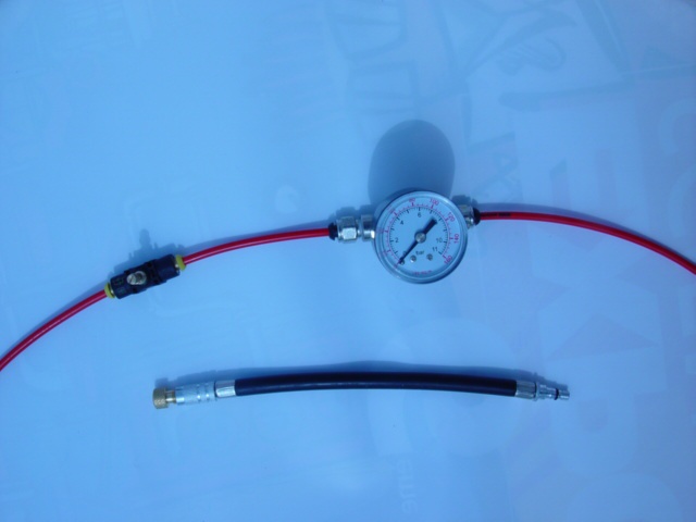
We use a good quality air pump with a pressure gauge incorporated that can supply pressures up to and including 10bar. In conjunction with a high pressure flexible adapter tube. Electric motor driven compressors connected to a reservoir are a good source of compressed air for multiple launches and competitions. We have recovered an old compressor from an air conditioning plant. Coupled to a pressure regulator and reservoir. Which we used for ‘ExpoScience’ demonstration launches. This guarantees a regulated supply pressure up to 35 bar!
Make sure that the rate of pressure increase is controlled by using a air flow regulator valve. This should be installed into the air pressure feed line before the pressure gauge that measures the pressure being supplied to the rocket. This is to control the rate of pressure increase and prevent a step change of pressure that could explode the plastic bottle. Start with the valve almost closed and experiment to find at what setting gives a progressive pressure increase to achieve launch pressure over a period of 20 seconds.
Alternatively it has been suggested that we can use a regulated air supply from an old scuba diving air tank. |
|
||
To prepare the parachute nose module and fold the parachute. Test the nose separation angle for subsequent flight clearance. Check dynamic stability by finding the centre of mass for the unfuelled rocket M2 and reset nose mass. Set mass centre to be one rocket diameter above aerodynamic centre of drag.
|
|||
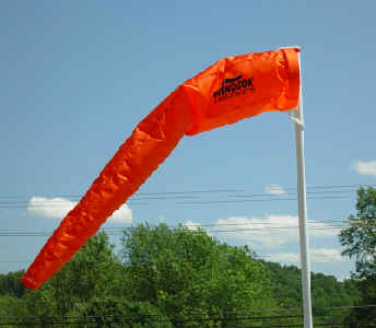
Wind velocity and direction. Calculate recovery distance. Air temperature. Atmospheric pressure. Measuring wind velocity and direction One of the simplest methods of measuring wind speed and direction is by using a wind sock. The velocity is indicated by the angle of the wind sock relative to the vertical. When there is no wind the wind sock does not inflate and hangs vertically. When there is a high wind velocity the wind sock inflates and is horizontal to the ground. Since the wind sock is pivoted it will also stream out in the direction of the wind. So indicating the velocity and direction of the wind to be found at the height of the wind sock. Note: There is a restriction when measuring wind speed at ground level. In that it will not necessarily be the same at higher altitudes.
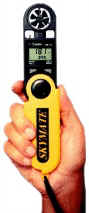
A more accurate but more expensive method is to use a air flow velocity meter. That measures the wind velocity using air flow driven fan or propeller. A unit like this can be used to calibrate the windsock. By creating a graph of windsock angle to measured air speed. Knowledge of wind direction is also important for determining the direction of flight of a launched rocket.
Basics When you have none of these available. We frequently take a hand full of grass and release it. Checking which way it falls aided by the wind. If it falls vertically it is almost calm at ground level.
Look for other signs that indicate the direction of the wind:
|

|
||

|

|
||
We have improved our parachute deployment during successive launches by reducing the build up of electro-static charge in the rocket nose cone. Flight data recording. Delicate digital electronics for recording flight test data do not like an environment that is heavily charged with static electricity. We have created a good earth by drilling the ground close to the launch site and installing a good earth strap that we attach to the metal of the launch tube. Refer to Electrostatic charge. |
|
||
|
|
|||
|
Photographs and short video clips are very useful due to the launch velocity and speed of flight involved. Analysis of launch and flight recordings using VirtualDub helps slow down the events and makes it easier to understand what happens. Analysing the events image by image. Launch velocities and accelerations can be estimated by referring to a fixed height marker next to the launch site. A scaling tower. I have encouraged Alexandre and Gabriel to use the digital camera to record events so that we can analyse them later. So our project has been well documented with photographs and short 16s videos.
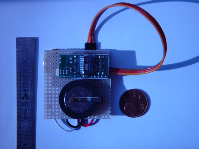
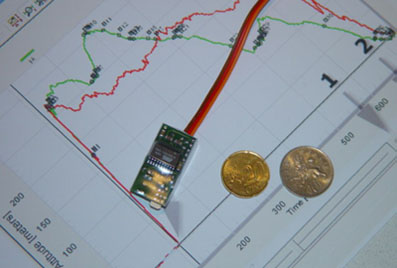
Launch and rocket flight data recording. Using electronic data recording downloaded after the flight to a portable computer. This can then be used to develop a more representative flight simulation mathematical model or program.
|
|
||
|
|
|||
We have recorded all our experiments and test launches using a Sony Cybershot DSC F707 digital camera with*10 optical zoom. |
|||
|
|
|||
|
Pre-launch sequence.
1.Install water and air feed lines then rocket.
|
|||

2.Install nose cone module and tape in position.
|
|||

3.Fuel with water to correct level required and adjust rocket to the vertical before locking launcher clamp.
|
|||

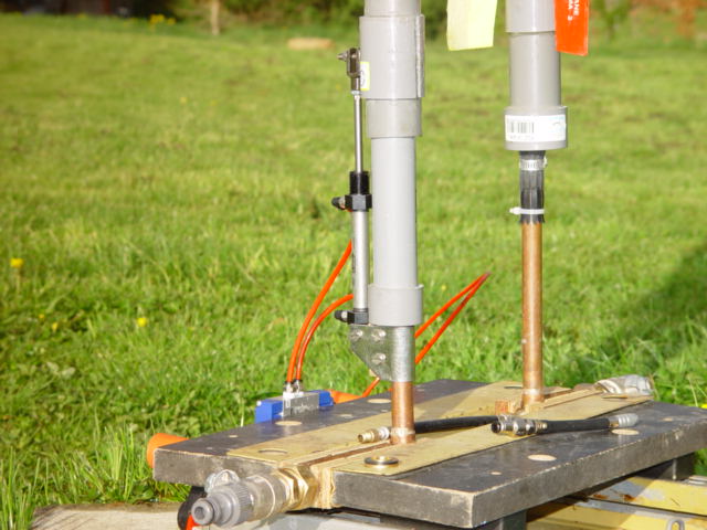
4.Disconnect hose and leave safety valve ready to dump pressure if required during pressurising or pre launch checks. Note: Here the pressure valve has been opened to show it in the safety pressure release position.
|
|||
| 5. Fold and install parachute and nose cone. Check balance mass. | |||
| 6. Check electronic flight data logger. | |||
| 7. Secure launch site with launch crew upwind. | |||
|
8. Slowly start to pressurise the rocket to the required launch pressure using the hand pump or compressor. |
|||
|
9.Start flight data logger by pulling flag.
10.Give instruction to start filming |
|||
| 11 Launch | |||
|
12.Observe flight.
13.Recover rocket
!4.Hold flight debrief. |
|||
|
|
|||
|
|
||
|
|
|||
10/12/05 This site was created on the 15th April 2003
©John Gwynn and sons2003
You're welcome to reproduce any material on this site for educational or other non commercial purposes
as long as you give us proper credit (by referring to "The Water-Rocket Explorer" http://waterocket.explorer.free.fr).