|
How
to design a parachute.
Controlling static electric charge. How to make a Huygens type parachute Parachute videos comparing standard with Huygens Alternative parachute release mechanisms
|
|
|
For instructions in
how to manufacture a parachute look at the workshop page.
|
|
|
Need to know what size of parachute you need
Parameters for calculating the size of parachute you need to safely recover your rocket or lander module with mass M kgs Change the parameters for mass and parachute diameter to obtain the required rate of descent. Make sure the ratio Fd / mg is equal to unity |
|
|
Fd = 0,5(de)(Cd)A(V2+Vair) 2
|
|
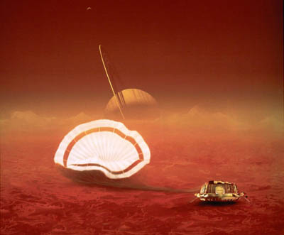
Its always nice when you get a soft landing. Its even better when it is 1.2 *109 Kms away on another planet.Titan. So you need to design and develop you recovery system to guarantee a good landing http://www.youtube.com/watch?v=SedRrGuT8Kg
|
|
Watch the images filmed by the probe as it descends through the atmosphere of Titan and lands on the surface.
|
|
|
|
|
|
|
|
|
|
|
|
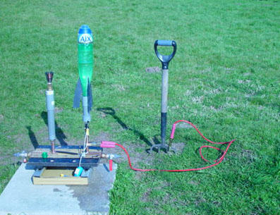
Controlling the build up of electro-static charge is important. Our simple solution was to earth the launcher tube using a battery jump lead coupled to a garden fork stuck into the ground. Subsequently we drove an long earthing metal spike into the ground close to the launch pad and coupled a good diameter cable to the launching tube. Or simply use a garden fork stuck into the ground. Which has a dual function of holding parachutes modules in place before they are mounted on the rocket. This is helpful when there is a strong cross wind at the launch site. You might ask .Why bother... If you are carrying out multiple launches with the same rocket beware of the cumulative build up of electro static charge in the nose cone. Another earthing loop system is to use a cold water feed pipe coupled directly to the launch tube. So that during fueling the launch tube is earthed. |
|
|
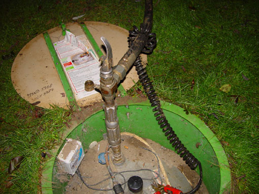
An example of electro static charge causing a potential problem in everyday life. High electro- static charges generated by the wheels of delivery vehicles rubbing frequently against the road surface could discharge and ignite liquified gas being delivered to a customer. Remember that little electric shock you get sometimes when you get out of the car and touch the ground. That is because the rubber compound used to manufacture the tyres effectively insulates the steel car structure from the ground, allowing an electro-static charge to build up as the tyres rub and generate friction on the road surface. To overcome this and reduce the number of gas delivery trucks that explode. An earthing cable is connected between the truck and the steel liquid gas reservoir of the customer. This earthing cable is incorporated into the outer layer of the gas delivery tube. The curly black cable in the above photograph is an example of an earthing cable which is clipped to the steel reservoir with a red pinch grip Once the static electricity is discharged then the gas is pumped into the customers reservoir.With no risk of an explosion due to static discharge. Why all this fuss about electro-static discharge. Well imagine what would happen when a space rocket was being charged with liquid oxygen and hydrogen if a tinny statiic discharge occurred. That's why safety procedures for real rockets discharge the rocket structure.
For water rockets the worst thing that can happen is that the parachute fails to open. Due to excessive static electricty sticking the parachute plastic canopy together. Or a highly charged rocket structure interfering with the functioning of micro electronic processor used for flight data logging.. So you loose some data.
|
|
|
|
|
Parachute packing |
|
 |
 |
|
When you get a little experience you can start using multiple parachutes. The two images above show the arrangement for packing a double parachute. One for recovering the nose cone and the second for the rocket.
|
|
Note: When using plastic or synthetic material for parachutes it is advised to use a light dusting of talcum powder to help the folded surfaces of the parachute canopy slide over each other during the pre inflation unfolding sequence. This to some extent helps overcome static charge sticking the plastic surfaces together.
|
|

|
|
 |
Carefully coil parachute cords |
 |
Fold parachute canopy into flat zig-zag. |
 |
Now vertically fold zig zag and pinch between finger and thumb placing it at the center of the base plate before installing nose cone. |
 |
The nose cone should sit comfortably on the shock plate without being lifted off by the spring of the folded parachute canopy. Should this be the case then repeat the procedure refolding the parachute. Reducing its packing volume by using a tighter pleating procedure. It is advisable to fold the parachute just prior to launch. So that the folded parachute has had less time to start expanding inside the parachute nose cone. Due to the plastic memory of the material trying to return to its original unfolded shape. |
|
|
|
Parachute material memory comparisonThis is the ability of a folded plastic parachute canopy to return to its original shape. Some plastic materials are more spring like than others so there response times are quicker.
|
|
|
Stiff reflective parachute made from emergency exposure blanket. Retains zig-zag form that could retard canopy opening. |
|
|
Light weight bin liner parachute. Slower to recover. But does not retain its sharp pleated zig-zag form.
|
|
|
The parachute loft. If possible always leave your parachutes unfolded when not in use. This helps the material preserve its unfolded shape naturally> This is again due to the memory of the material which is due to the individual fibers wanting to return to its original shape. Storing the parachute module with the parachute hanging from a shelf in the study or in a dry or in a dry storage room or classroom is ideal. This should be done for 24hrs before launch.
|
|
 |
|
|
|
|
Cord attachment
The 'Alexander' knot. Sealed or knotted end of the cord is placed just above the 'Duck' tape strip and the cord wound round the tape in a single loop. Before the cord and tape is attached to the edge of the parachute. Then a small length of normal sellotape is stuck across the cord loop face to reduce snagging. This system has yet to fail.
Previous causes of failure : Previously we had cords pulling free. Tape coming unstuck due to moisture or rain. Low temperature adhesive failure. Shock cords pulling free from the center shock plate. With the parachute disappearing into the blue beyond as the rocket undertook an unplanned impact test. Parachute canopy failing to fully inflate due to excess adhesive tape sticking the two folded surfaces together. Or a hole repair leaving the sticky side of the tape exposed. .
Video of parachute semi inflation due to cords becoming detached28.2.03.
For those who suffer from parachute failure. Some encouraging news... Your not alone!
Nasa's recent 250 million, 3 year 'Genesis' space exploration mission around the sun. Recently piled into the ground at 280km/hr when both its parachute systems failed to function. The article fails to mention the size of the parts recovered after the impact...... To read the article featured in the Independent Sept2004.Click on the address below. A blur of speeding metal, then a cloud of dust as space mission plummets to EarthThe crew of the recovery helicopter hired from Hollywood watched in stunned silence as NASA's Genesis spacecraft screamed past at more than 250km/hr. Instead of floating gently out from beneath the clouds. Final note: Cause of parachute failure after examination of wreckage is now believed to be the inverted installation of accelerometers that where supposed to measure the deceleration through the earth's atmosphere on re-entry.
http://news.independent.co.uk/world/science_technology/story.jsp?story=559699 http://edition.cnn.com/2004/TECH/space/09/08/genesis.entry.cnn/
One things for sure I bet your water rocket didn't cost 250.106 US$
Wonder what the name of the engineer responsible is ? |
|
|
Cassini -Huygens Space mission
|
|
|
Timeline of the Huygens probe as it descends through the atmosphere of Titan the largest moon of Saturn. This gives an example of how a combination of different size parachutes and small drogue chutes are used to control the descent of an exploratory space probe. Remember this is all taking place 1.2* 109 Kms from Earth. So once the 'Huygens' probe had left Earth on its 3.2*109 Km voyage on 15th October 1997 There's not a lot physically you can do to change anything. Yet seven years and 3.2* 109 Kms later it has to function! The project cost about 1.46Euro/km.
|
|

Results from the Cassini-Huygens probe published 30th November 2005
|
|
|
Time (CET) |
Event |
| 6.51 |
Timer triggers power-up of onboard
electronics
|
| 11.13 | Huygens reaches 'interface
altitude' The 'interface altitude' is defined as 1270 kilometres above the surface of the moon where entry into Titan's atmosphere takes place.
|
| 11.17 | Pilot parachute deploys The parachute deploys when Huygens detects that it has slowed to 400 metres per second, at about 180 kilometres above Titan's surface. The pilot parachute is the probe's smallest, only 2.6 metres in diameter. Its sole purpose is to pull off the probe's rear cover, which protected Huygens from the frictional heat of entry. 2.5 seconds after the pilot parachute is deployed, the rear cover is released and the pilot parachute is pulled away. The main parachute, which is 8.3 metres in diameter, unfurls.
|
| 11.18 | Huygens begins transmitting to Cassini and front
shield released At about 160 kilometres above the surface, the front shield is released. 42 seconds after the pilot parachute is deployed, inlet ports are opened up for the Gas Chromatograph Mass Spectrometer and Aerosol Collector Pyrolyser instruments, and booms are extended to expose the Huygens Atmospheric Structure Instruments. The Descent Imager/Spectral Radiometer will capture its first panorama, and it will continue capturing images and spectral data throughout the descent. The Surface Science Package will also be switched on, measuring atmospheric properties.
|
| 11.32 | Main
parachute separates and drogue parachute
deploys The drogue parachute is 3 metres in diameter. At this level in the atmosphere, about 125 kilometres in altitude, the large main parachute would slow Huygens down so much that the batteries would not last for the entire descent to the surface. The drogue parachute will allow it to descend at the right pace to gather the maximum amount of data.
|
| 11.49 | Surface proximity sensor
activated Until this point, all of Huygens's actions have been based on clock timers. At a height of 60 kilometres, it will be able to detect its own altitude using a pair of radar altimeters, which will be able to measure the exact distance to the surface. The probe will constantly monitor its spin rate and altitude and feed this information to the science instruments. All times after this are approximate.
|
| 12.57 | Gas
Chromatograph Mass Spectrometer begins sampling
atmosphere This is the last of Huygens's instruments to be activated fully. The descent is expected to take 137 minutes in total, plus or minus 15 minutes. Throughout its descent, the spacecraft will continue to spin at a rate of between 1 and 20 rotations per minute, allowing the camera and other instruments to see the entire panorama around the descending spacecraft.
|
| 13.30 | Descent Imager/Spectral Radiometer lamp turned
on Close to the surface, Huygens's camera instrument will turn on a light. The light is particularly important for the 'Spectral Radiometer' part of the instrument to determine the composition of Titan's surface accurately.
|
| 13.34 | Surface touchdown This time may vary by plus or minus 15 minutes depending on how Titan's atmosphere and winds affect Huygens's parachuting descent. Huygens will hit the surface at a speed of 5-6 metres per second. Huygens could land on a hard surface of rock or ice or possibly land on an ethane sea. In either case, Huygens's Surface Science Package is designed to capture every piece of information about the surface that can be determined in the three remaining minutes that Huygens is designed to survive after landing.
|
| 15.44 | Cassini stops collecting data Huygens's landing site drops below Titan's horizon as seen by Cassini and the orbiter stops collecting data. Cassini will listen for Huygens's signal as long as there is the slightest possibility that it can be detected. Once Huygens's landing site disappears below the horizon, there's no more chance of signal, and Huygens's work is finished.
|
| 16.14 | First data sent to Earth Cassini first turns its high-gain antenna to point towards Earth and then sends the first packet of data. Getting data from Cassini to Earth is now routine, but for the Huygens mission, additional safeguards are put in place to make sure that none of Huygens's data are lost. Giant radio antennas around the world will listen for Cassini as the orbiter relays repeated copies of Huygens data. |
| Specification
and timeline courtesy esa
http://www.esa.int/export/esaCP/SEMIEPQ3K3E_index_0.html
|
|
|
Huygens Technical Specification: Parachute system Launch mass of combined Cassini-Huygens space module 5548Kgs. Space probe mass sent into the atmosphere of Titan m = 320Kgs. Probe diameter 2.7m The 140mins descent through Titans atmosphere started at 11:13 CET 14.1.05 At 1270 km above the surface. The space probe needed to decelerate from 6 Km/s > to 6m/s. Entry angle 65degrees at 6 Kms/sec. After 3mins 6Kms/s > 400m/s. pilot 2.6m diameter parachute deployed for 2.5seconds.removing top cover. Main parachute of 8.3m diameter deployed. for 15mins. Main chute replaced by 3m diameter drogue chute for final descent of 120Kms. Note: Titan was discovered by Christiaan Huygens Dutch physicist and astronomer in 1655.
|
|

Image taken by the Huygens probe on the surface on Titan
|
|
|
|
|
|
How to make a 'Huygens' type parachute for your water rocket. Second level Parachute Read the instructions on how to make a simple parachute and then follow the instructions below. This type of vented canopy parachute is more stable than a simple parachute normally used for rockets. Its a little more difficult to make but try it and see if you can identify any difference in the stability of the descent.
|
|
|
'The Water Rocket Explorer' Huygens type parachute The jelly fish
|
|
|
The center canopy should be of a diameter 600mm.
|
|
|
So mark out the radius of 300mm using the same as
for the simple canopy.
|
|
 |
Then using the same center point mark out two
further radii of 320mm and 350mm. That will define the outer
stabiliser band.
|
 |
Cut out the 350mm radius canopy and fold four times to create 16 segments. Open canopy and mark out the 16 divisions by marking where each fold crosses the 350 and 305mm diameter. Before cutting out the inner canopy and outer band.
|
|
Cut eight lengths of cord1400mm long. Seal each end to stop fraying and fold each in two and attach to the shock ring as before.
|
|
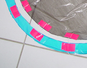 |
Then layout the center canopy and the outer ring
flat on the floor and systematically attach each end to the edge of center
350mm canopy. Using the Alexander knot and some duck tape. Then leaving an
even gap around the center canopy pull the cord so that it is normal
to the edge and use a second length of Duck tape to
attach the cord to the outer stabiliser ring
|
|
Make sure the duck tape will be on the outside of the
finished canopy.
|
|
 |
Attach a length of thicker shock cord to the
shock ring by folding it in two. Then pass the loop through
the shock ring and create a slip knot by passing the two free ends
through the cord loop.
|
| Finally attach the shock cord to the parachute module. By passing the two free ends through a hole drilled in the center of the shock plate and securing to the underside with two lengths of duck tape | |
| Ideally the outer stabiliser ring should be of a thicker plastic whilst the inner canopy can be made from a light weight plastic bin liner. | |
|
If in doubt refer to the images that illustrate how to build a basic parachute.
|
|
|
The gap between the inner canopy and the outer ring and can be altered to tune the descent required. Depending on the mass to be supported the daimeter of the parachute canopy should be chanaged to suit. |
|
|
Initial performance comparisons of Standard and vented Huygens 70cm diameter parachutes attached to nose cone module of mass m = 47gms.
|
|

|
Standard 8 cord 70cm parachute canopy in cross wind. To analyse films image by image use virtualdub |

|
Vented Huygen's type 16 cord parachute |
|
|
Vented Huygen's type 16 cord parachute in cross wind |
|
|
|
|
Alternative Parachute release Mechanisms. Fixed cord and elastic band release system. The elastic band or spring energy is released by a variable timer system. Using a minature clockwork 'tomy timer'. The nose cone is held in position by a fixed cord on one side and a tensioned elastic band on the other. When either the elastic band or the cord is released the nose cone is opened and flung away from the base module. This is usually an external release system but it can be incorporated within the nose module to reduce aerodynamic drag. Important design detail: Note: Shock base plate to absorb initial high acceleration loads and double cone location collar. |
|
 |
|
|
Video of nose cone release with timer set at 2secs.
|
|

|
|
|
Using a table or desk as a test bench. With timer clamped to leg of table. You can adjust the tensioning length and test release times. Before mounting the system on your rocket.
|
|
|
Materials required.
|
|
|
Test Procedure
Tape the base of the nose cone module to the surface of the desk or work surface. Attach a cord to one side of the nose cone pull tight and tape to the work surface. Attach a second cord to the opposite side of the nose cone and attach an elastic band. At the free end of the main elastic band attach a smaller elastic band. Which we will use to attach the tensioned elastic to the timer release. Drill a fine hole through the plastic head of the winding head for the timer and bond in a short length of steel wire cut from a paperclip. This will be used to hook the elastic. Note the sense of rotation of the winder when it is released . Stretch the elastic band and clamp the timer to the table leg adjacent to where the elastic has reached.. Wind up timer and attach the end of the stretched elastic band. Preventing the timer from runnning When ready. Release timer winder.
Note: The timer mechanism can be temporarily blocked by jamming the mechanism using a small strip of plastic then removing it to trigger the start. Once your happy that the system is reliable and opens at the time you want after launch . Install on rocket and test your new parachute deployment.
|
|
|
Click to enlarge image
|
|
|
02/10/06 |
|
©John Gwynn and sons2003
This site was created on the 15th April 2003
You're welcome to reproduce any material on this site for educational or other non commercial purposes
as long as you give us proper credit
(by referring to "The Water-Rocket Explorer" http://waterocket.explorer.free.fr).