This site was created on the 15th April 2003
Last update : 10/04/07
|
|

|
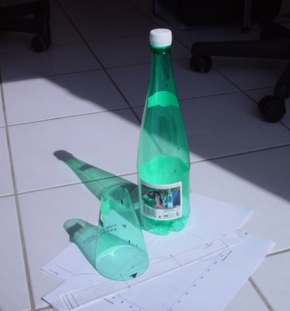
Choosing a bottle.
There are a lot of fizzy drink bottles that you can find in any supermarket. PETE plastic bottles come in a large variety of shapes and sizes.
Note: Some of our best water rockets are made from 1000ml Badoit bottles. So this new addition of the 75ml bottle could produce some interesting flights and a potential new second stage.
|
||||||||||||||||||||||||
|
|
|||||||||||||||||||||||||
|
|
Making the
rocket-First Stage propulsor
The following procedure is not difficult but accuracy is very important to guarantee good stable flight trajectory later on.
|
||||||||||||||||||||||||
|
|
|
||||||||||||||||||||||||
|
|
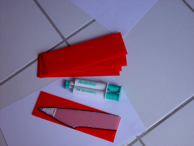
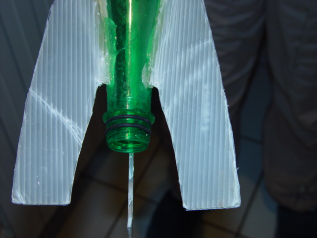
Materials for making the fins needs to be light so you can choose from what materials are available. · Balsa. · Polystyrene. · Plastic strips cut from the side wall of a bottle. · My preference is to use 'Flyweight' cellular corrugated plastic. That is both ultra light, tough and resists impact damage. Cut the form of the fin so that the cells rundown the length. |
||||||||||||||||||||||||
|
|
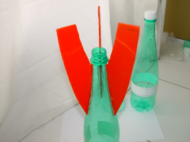
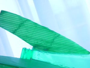
Bonding the fins to the bottle surface.
|
||||||||||||||||||||||||
|
|
Choice of adhesive.
· Rapid air cured 2 part expoxy. · Hot melt. · Toughened adhesive systems. · Polyurethane sealants.
For our demonstration rocket we will use an air cured 2part epoxy that cures in 90secs.
Note it is not advised to use urethane sealants other than in compression areas in the nose cone module where impact loadings are experienced. Ideally a toughened adhesive system should be used.
Note: This depends on the reliability of your rocket recovery system/parachute If everybody is honest it is rarely 100%.
|
||||||||||||||||||||||||
 |
Modular fins for staging are a development of this idea | ||||||||||||||||||||||||
 |
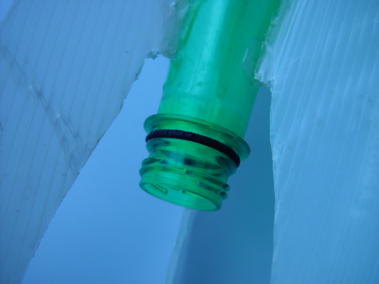
Making a pressure seal in the tube type launcher.
We use two No.14( 18.4*2.7mm) tap 'O' rings. On the external threaded neck of the bottle. Making the neck a piston fit inside the tulip cup of the launcher tube. Replace the 'O' rings when they become worn or begin to show signs of cracking. |
||||||||||||||||||||||||
 |
|||||||||||||||||||||||||
|
|
|||||||||||||||||||||||||
|
|
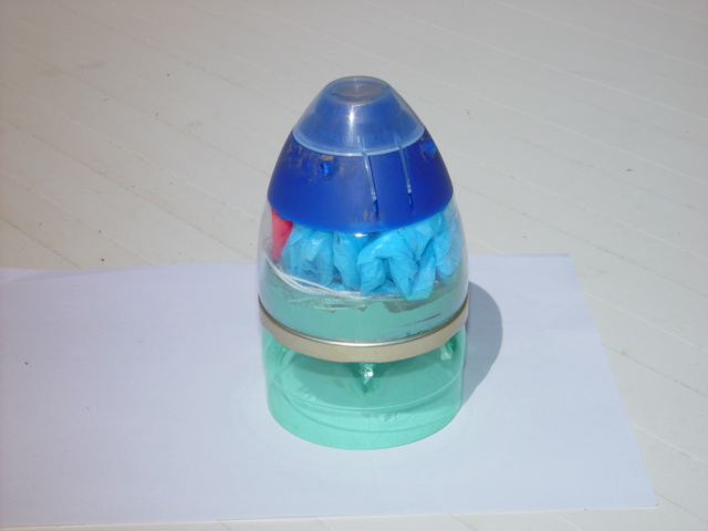
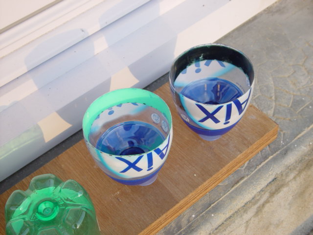
A simple and basic nose cone can be manufactured simply from a block of polystyrene foam recovered from some discarded packaging.
This type of nose cone will avoid a lot of the impact damage to either the landing site or the rocket. It is advised to manufacture a couple of spare nose cones to speed up replacing damaged nose cones or replacing lost or damaged rockets.
|
||||||||||||||||||||||||
|
|
A modular system means that you can change the module from one rocket to another or replace it with a nose module carrying a larger parachute. Specialised modules can be built later to carry cameras or measuring instrumentation to record flight data. As an introduction I have chosen one of our designs that has proved tough and reliable.
|
||||||||||||||||||||||||
|
|
The ‘Aerocoiffe’© This particular design is for using with a Badoit1L based rocket which is a safe platform from which to start experimenting.
Manufacturing Procedure for modular nose cone Capsule:
|
||||||||||||||||||||||||
|
|
|
||||||||||||||||||||||||
|
|
Making the ‘Shock plate’©
|
||||||||||||||||||||||||
 |
|
||||||||||||||||||||||||
|
|
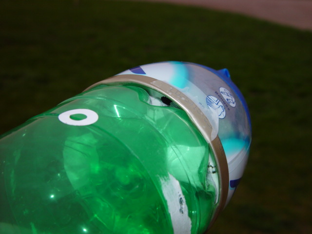
I use small pilot holes then drill them out to the larger final size. These are the launch pressure equalisation holes. Localised Aerodynamic turbulence causes a drop in pressure within the capsule that keeps the nose cone in place until the velocity of the rocket has reduced near the top of its flight.
It should not be either too tight or too slack. Allowing the nose cone to fall away when the base module is tipped.
|
||||||||||||||||||||||||
|
|
||||||||||||||||||||||||
|
|
|
||||||||||||||||||||||||
|
For higher acceleration loads we use a double taper cone. This stiffens the lower lip of the the nose cone and controls the cone release. This is done by selecting the cone band that smoothly fits over the shock plate collar. Then bonding it inside the open end of the nose cone using polyurethane sealant. We use the same collar arrangement for locating intermediary stages and modules. |
||||||||||||||||||||||||
|
|
Links: Good nose cone design |
||||||||||||||||||||||||
|
|
|||||||||||||||||||||||||
|
|
Making a parachute | ||||||||||||||||||||||||
|
|
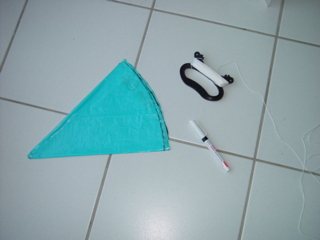
Making a parachute is relatively easy. Our main objective is to recover the rocket without damage so a parachute system that is reliable is essential.
For larger rockets or longer decent times you will need a larger diameter than for smaller rockets or minimum recovery time.
Here we will take a parachute that has been developed for the rocket nose cone above made earlier.
|
||||||||||||||||||||||||
 |
|
||||||||||||||||||||||||
|
|
|
||||||||||||||||||||||||

|
|
||||||||||||||||||||||||

|
|
||||||||||||||||||||||||
|
|
|
||||||||||||||||||||||||
 |
|
||||||||||||||||||||||||
 |
|||||||||||||||||||||||||
| How the make a Huygens type probe parachute. | |||||||||||||||||||||||||
|
|||||||||||||||||||||||||
|
|
|||||||||||||||||||||||||
| Making a launcher | |||||||||||||||||||||||||
|
|
Launch pad or Pas de tir
High pressure tested fully brazed tube launcher system with coaxial release collar. Quick release water coupling and safety pressure dump valve. Compressed air coupling using threaded adapter with high pressure flexible extension.
Multiple adapters for changing from standard tyre valve thread to micro bore plastic tube push lock fittings Instructions for manufacture are being prepared. Materials list spreadsheet with costs. Click here. For schools, colleges and universities we are able to supply launchers and flight data loggers. Contact us for details. Contact us
|
||||||||||||||||||||||||

|
Two sizes of PVC tube 40mm and 32mm outside diameter OD. These are used to manufacture the slide release collar. Copper tube 16mm OD |
||||||||||||||||||||||||

|
16mm copper tube ' T ' piece' | ||||||||||||||||||||||||

|
16mm to 28mm adapter neck.
This is where the neck of the bottle will fit inside with the flange resting on the top of the 28mm outlet throat. |
||||||||||||||||||||||||

|
16mm olive compression fitting to 1/2inch female. Use white teflon thread tape to seal the threads. Note:1/2inch or whatever the ball valve fitting requires. |
||||||||||||||||||||||||

|
Remove the two brass end nuts from the compression fitting and
with a half round file open out the internal diameter from 18mm to
20.5mm.
This 18mm double compression fitting has two rubber clamping seal rings. Which we need to hold the 10 black cable ties in place. Note: This replaces the adjustable hose clips which we had found to be unreliable when they stripped. Making the launcher unsafe. The head of the adjusting screw caused the release mechanism to be offset and not aligned with axis of the launch tube. Causing the release to be uneven.
|
||||||||||||||||||||||||

|
Cut three lengths of 16mm copper tube L = 450mm L = 90mm L = 70mm Lightly file square the tube ends and clean with some fine emery paper removing any grease from the surface before silver brazing. Allow to cool and then slide the modified 18mm compression fitting over the end of long length and slide to the bottom before brazing the 16 to 28mm adapter to the top of the free end.
Note: Brazing can be replaced by bonding the joints using a toughened engineering two part epoxy adhesive and placing in an oven at 80C for the cure time of the adhesive.
|
||||||||||||||||||||||||
|
Assemble the emergency ball valve to the 1/2 inch adapter followed by
the 'Gardena' pvc quick hose coupling for the water feed. Then mount the
flexible air pressure coupling onto the Schrader thread end.
|
||||||||||||||||||||||||
|
|
|||||||||||||||||||||||||

|
Thread the cable ties one by one under the two rubber compression rings
and set the grip length before tightening the two compression nuts.
Grip length adjustment is achieved using a cut off bottle neck inserted into the launcher release throat. Slide each cable tie by pulling on the free end until it clamps the top of the bottle neck flange and repeat for all the cable ties in turn working around the circumference. Potential movement under pressure is avoided by locking the double compression fixing at the step joint created at the interface between the the 28mm adapter and the 16mm copper tube. This shoulder stops the fitting sliding up.
Alternatively use a good quality stainless steel 'Norma' adjustable hose clip. Clamped between the compression fitting and the shoulder. Here the hose clamp is no longer required to take any major loading .It provides a compressive stop between the shoulder and the top of the compression fitting.
Then slide over the larger 40mm OD PVC locking tube. The lower end of which is located axially by a smaller 32mm OD tube passing inside and acting as a guide.
|
||||||||||||||||||||||||
|
Pressure test the launcher after completely filling both the launcher
tube and
bottle with water.
Readjust and tighten. Recording the test date on a sticker prominently displayed on outside of the launcher tube. Retest and adjust at the start of every season/academic year. |
|||||||||||||||||||||||||

|
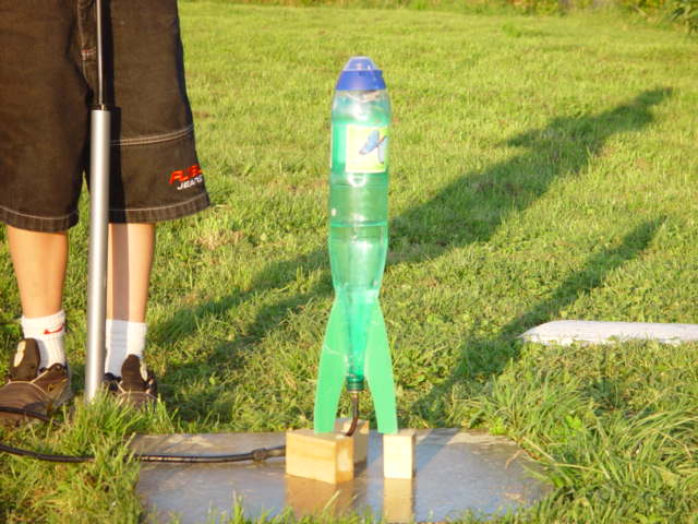
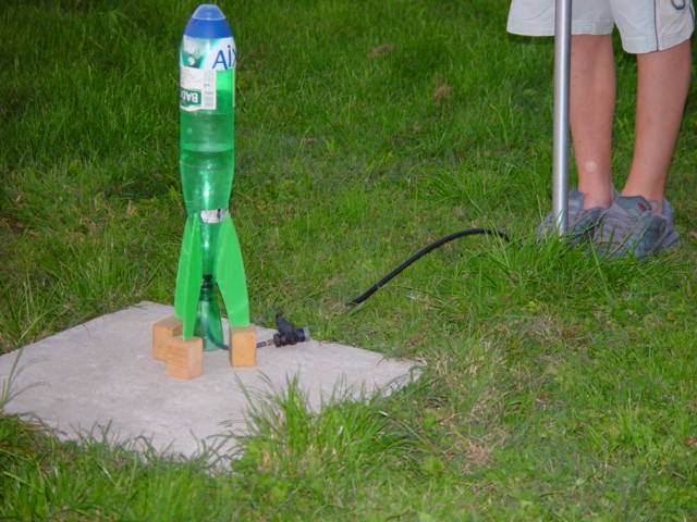
To firmly clamp the launcher tube we use two strips of 20mm plywood that have been drilled out along the the center to produce spacer blocks that then locate around the bottom T piece. Preventing the tube from being locally crushed when clamped in the vise of the workbench. | ||||||||||||||||||||||||
|
Using the packing blocks either side of the launcher tube base. Clamp it in position using the vise of a mini Black and Decker work bench. Or equivalent. We install this on top of a leveled concrete slab . So no matter where the launch site is you always have stable platform from which to launch. To set the launcher tube vertical we use the liquid level in the rocket bottle as a spirit level. Adjusting the inclination axis of the tube to obtain the desired inclination before final clamping.
|
|||||||||||||||||||||||||
|
How to make a
simple plug launcher
|
|||||||||||||||||||||||||
|
List of Materials required:
1* Car tyre or bicycle inner tube pressure valve. 1* Cider bottle cork Flexible extension to connect tyre pump to the pressure valve. A good tyre pump with a pressure gauge incoporated. A drill of the same diameter as the tyre valve stem.. Urethane sealant Sika flex. Masking tape
|
||||||||||||||||||||||||
|
Note: The plug being ejected from the bottle is what will eventually release the rocket.
|
||||||||||||||||||||||||
|
|
||||||||||||||||||||||||
|
|
|||||||||||||||||||||||||
|
|
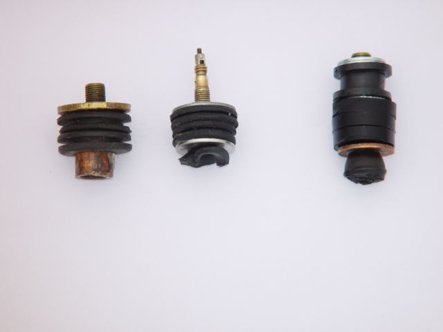
Mk 2
Plug
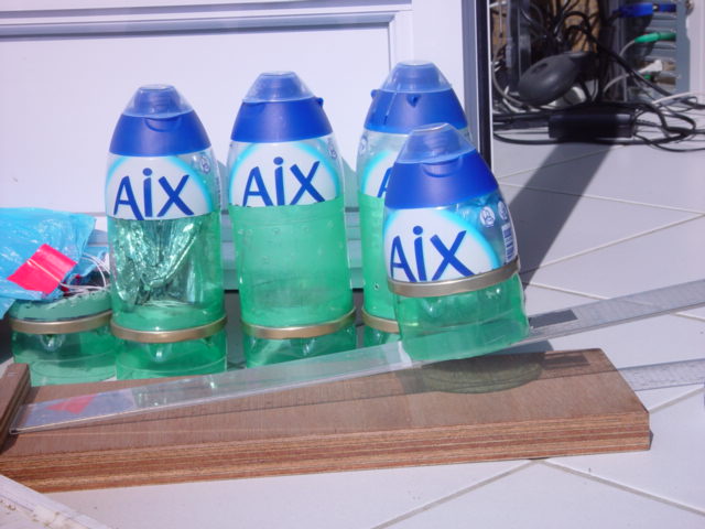
Our Development of the plug launcher . To obtain a better seal and a longer plug life we found several ways of replacing the cork with drilled out tap washers and rubber panel grommets.
|
||||||||||||||||||||||||
|
|
Mk3 plug This is a little more sophisticated and uses the clamping nut on the bicycle tyre valve to clamp the rubber piston made up from rubber grommets. Which expands the rubber piston diameter once it is inside the neck of the bottle
This simplifies the procedure to install the plug into the neck of the bottle. With the final expansion of the seal being done by tightening the clamping nut using a small spanner. In the image the smaller diameter bicycle valve plugs are the 2nd and 3rd from the left. Click on the photograph to obtain a larger image.
|
||||||||||||||||||||||||
|
|
|||||||||||||||||||||||||
As above but with refined pneumatic release actuator.
|
|||||||||||||||||||||||||

|
|
||||||||||||||||||||||||
|
|
|||||||||||||||||||||||||

|
Multi Stage Rockets
Inter-stage release as the first stage finishes and the second takes over are important in guaranting the continued progress and the acceleration of the remaining rocket mass Spider interstage release © September2003 This allows for the different stages to be charged independent |
||||||||||||||||||||||||

|
To maintain the aerodynamic surface between stages we use an inter
stage tube or cowl and folding sprung fins. That open on launching
the new stage..
The inter-stage tube is rejected with the first stage |
||||||||||||||||||||||||
|
|
|||||||||||||||||||||||||
Contact us for details. Contact us
|
|||||||||||||||||||||||||
|
|
Design and development
Fin shock loading at launch. Normal loading conditions will require the fins to support a simple compressive load made up from the mass of the rocket prior to launch. At launch the water jet force assumes the responsibility for this mass propelling the rocket into the atmosphere. Subsequently the loading on the fins becomes that introduced by the flight dynamics of the rocket. Flow induced dynamic 'Flutter' is to be avoided at the high initial flight velocities The main role of the fin surface is to stablise the direction of flight and avoid any major derive/deviation from the intended flight path.
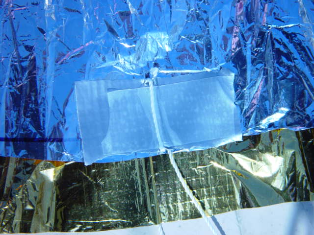
Exceptional fin loading occurs when the rocket explodes on the launch pad. With the direction of energy thrust being reversed. The adjacent photograph shows the compression shear stress marks that resulted. This type of compressive shear can also be induced when multistage rockets fall back to Earth immediately after launch due to insufficient initial thrust force being generated at launch. With the initial rocket mass M1 of the subsequent unused stages trying to crumple the fin panels as they impact the ground. " Great things are not done by impulse, but a
series of small things brought together". Ironic quotation which says that success is the result of assembling many simple existing systems or ideas in a new original way. |
||||||||||||||||||||||||
|
Understanding the need for rocket development and failure analysis |
|||||||||||||||||||||||||
|
Getting the water rocket design and development team to sit down and analyse why things did not work as planned is an integral part of any project. To understand that even the best engineers and scientists get it wrong sometimes is therefore a very healthy exercise. Whether your project is family or college based. Organise a de briefing meeting to discuss what went wrong. Analyse videos and get everybodies observations on the event. Before any conclusions are made. Do not believe in what your computer simulation tells you. Invariably what happens in the real world will be different. For all soughts of reasons. Practical experience is invaluable to develop a reliable launcher and flight programme.
Detailed analysis of failure can identify multiple causes that improve future reliability. The soviet Semoirika/Soyuz is a classic example. The Worlds most legendary launcher. Is based on minute detective work required to uncover the problems during its conception and development.
|
|||||||||||||||||||||||||
Design Creativity, 'Brain -Storming' and lateral thinking.
Using the water rocket project to introduce lateral thinking and creativity. http://www.edwdebono.com/debono/selfi.htm
|
|||||||||||||||||||||||||
 |
|||||||||||||||||||||||||
© John Gwynn and sons2003
You're welcome to reproduce any material on this site for educational or other non commercial purposes
as long as you give us proper credit (by referring to "The Water-Rocket Explorer" http://waterocket.explorer.free.fr).