|
|
Rocket Recovery Systems. |
|
These can be many and various and are a good opportunity to invent , prototype , experiment , develop ideas and discover .
A little pointer : Always analyse why something fails before throwing it into the bin and trying the next idea. Accurate identification of the causes of failure are important to achieving a success. What is a recovery system. This is an assembly of components that enable the launcher, coiffe or payload to be recovered undamaged and reusable with a 100% reliability. Within a defined environment. Well that’s the objective . What is required is some means of retarding the rate of fall during descent. This can be achieved by increasing the drag coefficient of the rocket during its descent phase. Typical ways of doing this are to increase the cross sectional area of the rocket by some means.
Increasing the surface area exposed to the slipstream.
Recovery system types.
|
|
1.Parachute deployment at fixed point during rocket flight. The highest point attained during the flight is taken to be the most suitable and is referred to as the 'apogee' of the rocket trajectory. The point furthest away from the earth. At apogee the recovery system needs to be deployed and can be triggered by either a mechanical or electronic timers, the use of an accelerometer or a system that monitors the change in external fluid flow.
2.Streamer or ‘Drag Tag’ to slow down descent. 3.Air brake flap system that opens during descent. .4. Rotating blades that retard descent.
Some type of retractable rotor that deploys at apogee and slows the descent.
5.Retro rockets that reduce velocity as the rocket approaches the ground.
6.Balloon deployment at apogee. Filled with helium or air. 7.Deployment of a delta glider winged descent.8.Deployment of para-glider chute that inflates forming a wing aerofoil section. 9.Gas damper nose cone. Used to absorb impact shock loading.
10.Collapsable impact absorbing structure. That is either sacrificial or recyclable. Impact absorbent honeycomb structures that absorb the high energy deceleration loading. The legs of the NASA moon lunar lander module where made from hollow telescopic legs filled with light aluminium honeycomb. That simply crushed on landing as the leg strut telescoped. Here the energy required to plastically collapse the aluminium honeycomb can be used to absorb the impact energy of the rocket and reduce severe levels of decceleration
11.Air flap timer release. Where the folding motion of a horizontal hinged air flap at launch is used to trigger a 'Tomy timer' or other delayed parachute release system. A small hole in the air flap is used to block the timer before launch. With the air flow over the rocket at launch folding the air flap and allowing the timer spindle to turn. |
|
Parachute 1 Simple parachute
Parachute 2 Huygens esa Timer release video |
|
|
|
Secondary energy absorption systems.
So what happens if your first level recovery system fails? This is where a secondary system will help protect your payload . Here are a few options: 1 Deployment of a smaller secondary parachute . 2. Incorporation of an impact energy absorbing layer,. Polystyrene, aluminium honeycomb below the nose module. 3.Rejection of nose cone mass to remove stability of flight. 4. Seperation induced by the relative aerodynamic drag force between nose cone and mass rocket body including fins. Fdrag Body >> Fdrag nose cone. Relative decceleration of main body and nose cone Fdrag Body / Body mass Fdrag Nose cone / Nose cone mass.
Energy Absorption |
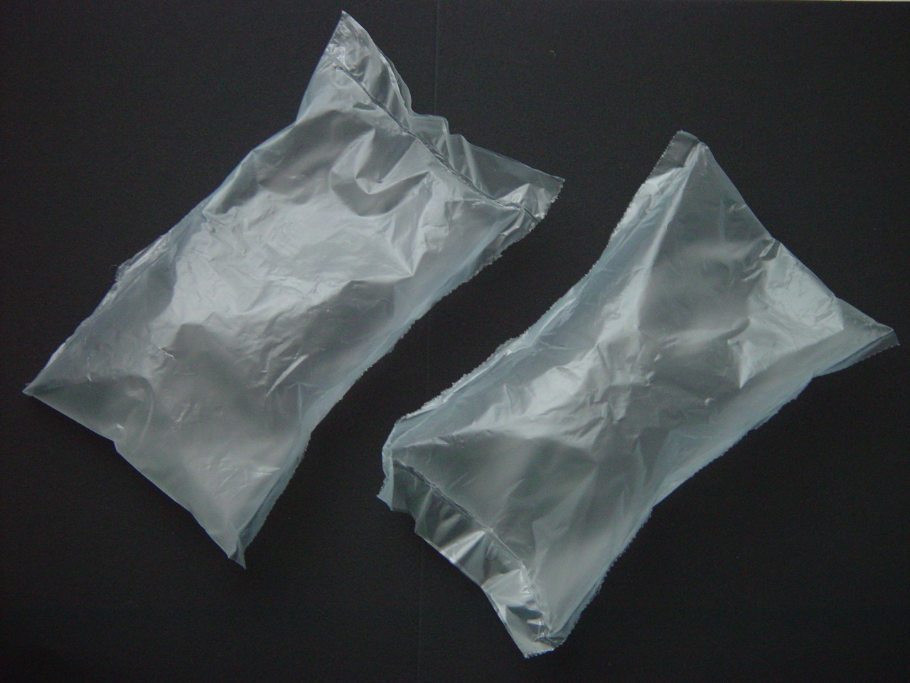
Air bag. These air filled plastic bags are currently used in light weight packaging.
|

Aluminium honeycomb |

Block of aluminium honeycomb after and before impact
|