|
|
|
|
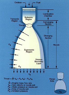
Thrust Force Fjet = q* Ve + ( Pe-Pa)*Se N
Where (q) is mass flow rate leaving the nozzle in Kgs/sec Ve Is the jet stream velocity m/s Pe Is the pressure of the fluid stream as it leaves the nozzle N/m2 Pa Is the atmospheric pressure outside the nozzle into which the jet stream passes. N/m2 Se Nozzle matching parameter.
Note : V2 Is the actual velocity of the rocket m/s |
|
|
Due to the ‘Tsiolkovski’ factor V2 can be greater than Ve. Looking at the formula for determining the jet thrust force that propels the rocket. We can say that Fjet is directly proportional too: q and Ve |
|
| Note: The example of a rocket engine comprising of a combustion chamber leading to a compression expansion nozzle can also be extended to explain the pressurised bottle and outlet nozzle used for a water rocket | |
|
Conclusions: To increase the jet thrust force Fjet to a maximum:
Fd = 0,5(de)(Cd)A(V2+Vair) 2 N Improving the aerodynamic shape and form . Reducing the value of Cd. If the nose cone resembles the shape of a brick then there is a considerable resistance created as the rocket punches its way through the atmosphere.
|
|
|
Once the fliud has past the nozzle throat the coefficient for the divergent part of the nozzle (Cf) smooths the transition of Pe>Pa reducing turbulent flow.
F= Pe*At*Cf N
Where : Pe is pressure of fluid jet at the nozzle. N/m2 (At) is the area of the nozzle throat m2
The change of Pa with increasing altitude can have a significant affect on the nozzle efficiency of large full size rockets. Due to the requirement of keeping a balanced ratio between Pe and Pa. Needed to keep the nozzle efficiency of the rocket engine at an optimum 'Design Point'. As the rocket passes through the Earth's atmosphere and into space.
What is important to observe from this graph is the progressive reduction in atmospheric pressure up to an altitude of 50 kms.
It is for this reason that the rocket jet plume cone angle for a fixed geometry divergent nozzle progressively changes as the rocket passes through the atmosphere.. Combined with the increase in rocket velocity and the reducing density of the atmosphere as the rocket climbs the plume exhaust cone angle leaving the nozzle increases. This can be seen after the first stage separation as the main stage takes over and accelerates through the reduced pressure of the upper atmosphere. A wonderful example of this can be seen in the Soyuz launch video found on the attached link.
So to match the nozzle geometry to the environment and maintain optimum efficiency. The nozzle ideally needs to be variable. One way of doing this is to use multiple stages with a different divergent nozzle design profile for each which is more adapted to operate at that altitude.
Another way of addressing this problem is by using a 'plug nozzle' or 'aero spike' jet nozzle by using the quality of the airflow over the external nozzle to provide the outer duct. These types of jet allow for a variable geometry expansion nozzle. Provided by the external accelerated air flow over the surface of the projectile.
Note: The difference between normal temperature 0C and degrees absolute 0K is 273. So to obtain temperatures in 0C subtract 273 from 0K values. Graph courtesy Cambridge University.
New Jet thrust force derivation Water Rocket Explorer PDF Summary Formula summary sheet for propulsion force, momentum and Tsiolkovski derivation PDF http://www.boeing.com/defense-space/space/propul/XRS2200.html http://www.aerospaceweb.org/design/aerospike/
|
|
|
Soyuz 'parasol' jet stream plume at high altitude |
|
|
Courtesy Boeing Aerospace
Understanding rocket propulsion http://www.braeunig.us/space/propuls.htm#intro
|
|
 Shuttle
main engine on test. Jet expansion Mach discs Shuttle
main engine on test. Jet expansion Mach discs |
|
|
|
|
|
|
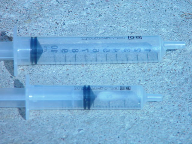
A simple experiment to get a feeling for creating a jet
|
|
|
|