top

Home ] workshop ] how does it work ] History of Astronautics page index ] Rocket launches ] useful sites ] version francaise ] Contact us ]


FLIGHT STABILITY


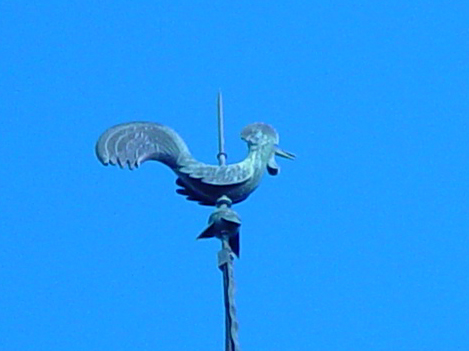
Weather vane which is designed to always point into the wind


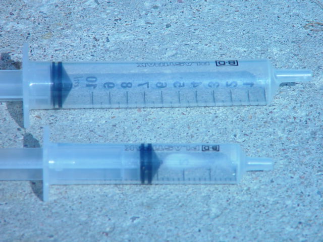
Flight stability is governed by the relative positions of the centers of mass Cm and the aerodynamic center Ca.

Some simple experiments:

Dsc01473.jpg (58073 bytes)    Balloon flight prediction.

Take an inflated balloon and release. The direction taken during its flight is erratic and it is very difficult to predict where it will go and what  flight path   ( trajectory) it will follow.

This random nature of converting compressed air into motion, is a good illustration of the elements we need to identify and control when converting the energy of the compressed air in our future water rocket into an efficient jet thrust force.


To establish if the flight trajectory is random you can develop a little game.

Mark a balloon launching point in the middle of room with a white cross. Then take a sample of balloons say 10 marking each with a number. Inflate the balloons in turn and release without tying a knot from the launching point timing each flight and filming several of the flights using a short video. Mark the point where the balloon lands and measure the distance from the original launch point.

Then with exactly the same balloon repeat the experiment and observe where the balloon lands.

Record all the data and ask those participating why the balloon flights vary and ask them to provide some explanation as to what parameters and variables could be involved.

To add another variation introduce different shapes of balloon at the end of the trial and one filled with helium with a small weight attached.

  • Why? We need to understand some of the basic parameters involved.

Some of the parameters involved:

  • Flexible jet duct nozzle. Giving variable direction jet thrust.

  • Aerodynamic ratio of length(L) to diameter (D)   L/D> 1. Giving an unstable form .With a degree of freedom to rotate about its own volume.

  • Center of mass Cm and aerodynamic center Ca  are too close to each other.


Dsc01480.jpg (62220 bytes)  Syringe jet

A simple fixed jet producing a directionally stable jet thrust force can be demonstrated by using  a syringe filled with water

  • Fill a syringe fill with water and expel the water using different piston speeds.

  • Then half fill the syringe water and the rest with air then depress the piston as fast as you can to expel the water /air charge. 

  • Look for the spray burst.


  How would you develop a balloon that is aerodynamically  more stable with a flight trajectory that is both stable and predictable? 

Have a go...

top


Unstable flight of a plastic bottle.

Take a plastic bottle without fins fill approximately one third full with water and pressurize with compressed air using one of the launching methods mentioned in the launching systems section. Make sure that the launch site is cleared before launch.

  • Observe how the bottle tumbles and twists erratically as it tries to penetrate the atmosphere. The energy given to the bottle by the jet is not converted into a stable flight trajectory. Absorbed by the turbulence created as the bottle tumbles out of control.  (Refer to video of unstable flight.)

  • This in part is due to the lack of an aerodynamic nose cone that will help control the air flowing over the surface of the rocket. In addition the relative  position of the two centers of mass Cm and aerodynamic drag Ca do not contribute to stable flight.

video  of Unstable flight of 1.5 l bottle without fins or modified center of mass

Unstable Image sequence71 > 120

Here the bottle tumbles chaotically out of control trying to decay the energy given to it at launch. Failing to follow a set direction given at the start of the flight .

Dsc02501.jpg (63212 bytes)

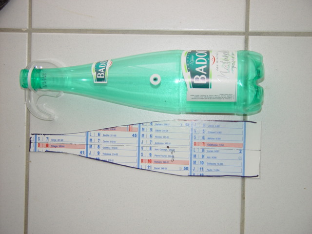
Above you can see a photograph of both   Cm  and Ca centers that have been found for a simple 'Badoit' bottle without fins and nose cone.

Note: The neck of the bottle and the equivalent datum of the flat card profile have then been set to the same reference datum before the photograph was taken.


The center of mass has been marked on the bottle by a black spot in the middle of a white ring. 


Whilst an approximation of the aerodynamic center Ca can be seen marked onto a piece of stiff card. That has been cut out to the exact profile of the bottle.

Note that for the normal bottle the center Ca is above the Cm. So in this configuration the bottle would be unstable. When launched as a rocket or as a projectile  towards the right of the screen.

top


Stable flight of a plastic bottle 


Manufacture a dynamically stable rocket from the same bottle fill with exactly the same volume of water and launch using the same method as used for

      Exp3.  Manufacturing a dynamically stable rocket.

  • Attach fins and a nose cone to the same bottle tested in Exp2 and determine the positions for the center of mass Cm and the aerodynamic center Ca .

  • Cm is found by taking the unfuelled rocket (including parachute) and finding the point along its length where it balances.

This can be done by suspending the rocket from a looped thread as seen in the photographs and changing the position of the cord until the bottle rests horizontal.

  • Once you have found this point mark it with either a indelible felt tip pen or preferably with white adhesive reinforcement hole stiffener. This I find is more legible and can be seen at a distance.

  • To find Ca this can be approximated by taking the rocket and marking out an exact profile of the rocket onto a large piece of stiff white card, thin aluminium sheet or plywood.

  • Cut out the flat profile and clean up the edges before finding its center of mass. This can be achieved by using a similar method used above or by using a fulcrum made simply from the edge of a ruler that has been stuck using 'blutak' to top of a horizontal surface. Sliding the cut out profile of the rocket across the edge of the ruler until a point of balance is found. Using a different colour mark the point on the surface and check by suspending the profile from the same point.

  • Now transfer the position of this Ca point to the rocket body.

Objective: The ideal is for the position of the center of mass Cm to be one rocket body diameter above the Ca (aerodynamic center:)

This condition will cause the aerodynamic forces to trail behind the center of mass and stabilise the flight path during its climb into the atmosphere.

A dynamic couple is created that stabilises flight trajectory. An example of this is that we have carried out over 100 flights without parachute that have landed within a radius of 20m and attained apogee where the rocket has disappeared from sight.250m+


Conditions that do not conform :

  • If the two centers are either at the same point (superimposed) or are too close to one another.

  • Or the aerodynamic center is above that of the center of mass.

Solutions to make these conditions conform to our objective are:

  • Alter the center of mass by changing the nose balance mass to shift the center of mass to the desired position. Check using the above method.

  • Change the aerodynamic profile to lower the Ca to the desired position.

  • Or a combination of the above that gives the lowest weight solution.

  • Now test the un-fueled rocket by suspending it from a nylon cord and take it outside when there is a strong wind blowing. see short video.

top

The weather vane

So why does a weather vane always face into the direction of the wind?

Note that the vertical axes about which the weather vane pivots is forward of the center of the cock. This will coincide with the center of mass of the bird  which  is a hollow structure and is usually fabricated out of  corrosion resistant metal sheet.

 Note: The head of the bird will be loaded whilst the tail will be hollow to bring the center of mass forward.


Next look at the large surface area of the tail of the bird relative to the neck and head. This will guarantee that the 

aerodynamic center or center of pressure is behind the pivot. You can try to imagine this as  a large single fin.

 The air-stream passing over the surface of the bird produces a resultant force acting through the center of pressure that produces a couple (or turning moment ) about the vertical axis  of the weather vane. Causing the  head of the bird to turn into the direction  the air-stream  or wind.

The above example of a rocket suspended from a thread placed above its center of mass turns into the direction of the air-stream in the same manner.


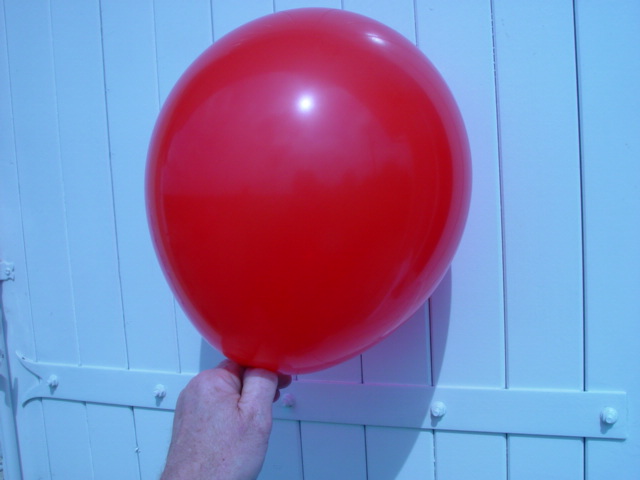
Aerodynamic Ratio Effect

For a given volume the ratio of length to diameter is important. L/D

  • Where D (diameter) is greater than L (length) then the object (in our case a rocket) will find it harder to penetrate the atmosphere after launch. Than say a rocket of the same volume but longer and of a smaller diameter. Where L is greater than >D.

  • A simple test is to take a large panel of plywood 1m*1m say and get one or two of the pupils to either stand out in a strong wind or run around with the panel held in front of them.

  • Note: Alternatively a large strong plastic sheet can be used. Held vertical by two participants.

    Then release one edge and let the sheet flap in the wind. Why are there holes cut into large banners on a protest march.?

  • Then repeat the test with the panel held edge into the wind or the direction which they run so reducing the exposed cross sectional area and reducing the aerodynamic drag force.

  • Riding a bicycle sat upright or in a bent forward position can affect free wheeling maximum velocity.


      Another experiment using helium filled balloons having the same volume of helium but balloons with different L/D ratios. 

      That are released within a large internal space such as a sports hall and timed to determine which balloon has the fastest rate     

      of climb.

     Height divided by time.

     Then discuss why there is a difference and what parameters could contribute.

Objectives:

  • When we need forms or projectiles to travel quickly then the cross section exposed to the direction of motion needs to be as small as possible and for any specific volume of projectile L>D.

  • Examples space rockets, F1 racing cars


  • When we need to retard or slow things down then we need to increase this same aerodynamic drag force to a maximum.

  • That is D>L for a specific volume as is the case say for a parachute where we increase the cross sectional area exposed to the upward air stream.

          By inflating a stable large cross section parachute


Another parameter that is important is that the directional stability of the jet impulse is constant.

We have assumed that the jet stream flowing from the nozzle of the stabilised rocket is constant and along the longitudinal axis of the rocket.

That is the nozzle is fixed along the longitudinal axis of the rocket and symmetrical..

top


Variable orientation expansion nozzles.

Safety Note: Variable direction expansion nozzles can be used to vary the flight trajectory profile. It is not recommended to experiment with these  until you have experienced a lot of successful launches with fixed nozzle rockets. Random flight direction stability similar to the balloon experiment can be expected.

Remote launching is essential for testing variable direction nozzles. Test on a remote test range with experienced adult supervision  The potential launch instability can be very dangerous. Please avoid the temptation to try these. Stick to the basics. All will come to those with the patience to be thorough.

Develop ideas using static tests to confirm the directional stability of expansion nozzles before test launching.

top

menu of this section ] next ]

04/05/06

This site was created on the 15th April 2003


 ŠJohn Gwynn and sons2003 

You're welcome to reproduce any material on this site for educational or other non commercial purposes

 as long as you give us proper credit (by referring to "The Water-Rocket Explorer" http://waterocket.explorer.free.fr).